А Б В Г Д Е Ж З И Й К Л М Н О П Р С Т У Ф Х Ц Ч Ш Щ Э Ю Я
печь, -и и печи́, тв. пе́чью, предл. в (на) печи́, мн. -и, пече́й
Рядом по алфавиту:
печи́ща , -и, тв. -ей (увелич. к печь)
печи́ще , -а (остатки развалившейся печи; семейная община на Русском Севере)
пе́чка , -и, р. мн. пе́чек
пе́чка-время́нка , пе́чки-время́нки
пе́чки-ла́вочки , другие формы не употр.
печни́к , -ика́
печно́й
Печо́рин , -а
печо́ринский
печо́ринство , -а
Печо́рская губа́ , (в Баренцевом море)
печо́рский , (от Печо́ра и Печо́ры)
Печо́рский , (у́гольный) бассе́йн
печо́рцы , -ев, ед. -рец, -рца, тв. -рцем
печу́рка , -и, р. мн. -рок
печь , -и и печи́, тв. пе́чью, предл. в (на) печи́, мн. -и, пече́й
пе́чь , пеку́, печёт, пеку́т; прош. пёк, пекла́
пе́чь-гри́ль , пе́чи́-гри́ля, ж.
пе́чь-калори́фер , пе́чи́-калори́фера, ж.
пе́чься , пеку́сь, печётся, пеку́тся; прош. пёкся, пекла́сь
пешава́рский , (от Пешава́р)
пе́ше-лы́жный
пешедра́лом , нареч. (сниж.)
пешехо́д , -а
пешехо́дка , -и, р. мн. -док (маршрут)
пешехо́дный
пе́шечка , -и, р. мн. -чек
пеше́чком , (устар. к пешо́чком)
пе́шечный
пе́ший
пе́шка , -и, р. мн. пе́шек
Как написать слово «печь» правильно? Где поставить ударение, сколько в слове ударных и безударных гласных и согласных букв? Как проверить слово «печь»?
пе́чь
Правильное написание — печь, ударение падает на букву: е.
Выделим согласные буквы — печь, к согласным относятся: п, ч, глухие согласные: п, ч.
Количество букв и слогов:
- букв — 4,
- слогов — 1,
- гласных — 1,
- согласных — 2.
Формы слова: печь 1, -и и -и́, тв. пе́чью, предл. в (на) печи́, мн. -и, -е́й.
Ответ:
Правильное написание слова — печь
Ударение и произношение — п`ечь
Значение слова -устройство или сооружение для обработки чего-нибудь нагреванием
Пример:
Пламенная п. Электрическая п. Плавильная п. Доменная п. Сушильная печь. О бжиговая п.
Выберите, на какой слог падает ударение в слове — ГРУНТОВЫЕ?
Слово состоит из букв:
П,
Е,
Ч,
Ь,
Похожие слова:
впечь
выпечь
выпечься
допечь
допечься
запечь
запечье
запечься
запечьям
запечьями
Рифма к слову печь
отвлечь, речь, сжечь, горечь, лечь, развлечь, сечь, сберечь, зажечь, прилечь, отпречь, стеречь, привлечь, беречь, картечь, течь, пересечь, поперечь, сволочь, точь, помочь, плачь, дочь, навзничь, очь, ночь, прочь, желчь, полночь
Толкование слова. Правильное произношение слова. Значение слова.
↳
печь — существительное, именительный п., жен. p., ед. ч.
↳
печь — существительное, винительный п., жен. p., ед. ч.
Часть речи: существительное
Часть речи: глагол
Часть речи: причастие
Действительное причастие:
Страдательное причастие:
| Настоящее время | ||||
|---|---|---|---|---|
| Единственное число | Множественное число | |||
| Мужской род | Женский род | Средний род | ||
| Им. | ||||
| Рд. | ||||
| Дт. | ||||
| Вн. | ||||
| Тв. | ||||
| Пр. |
Часть речи: кр. причастие
Страдательное причастие:
| Прошедшее время | |||
|---|---|---|---|
| Единственное число | Множественное число | ||
| Мужской род | Женский род | Средний род | |
|
печен |
печена |
печено |
печены |
Если вы нашли ошибку, пожалуйста, выделите фрагмент текста и нажмите Ctrl+Enter.
На чтение 2 мин Просмотров 293 Опубликовано 02.09.2021
Сомневаетесь в выборе корректного варианта, не знаете, как написать: печь или печ? Давайте разберёмся в вопросе вместе.
Как пишется правильно: печь или печ?
Мы имеем дело либо с существительным, которое имеет значение «нагревательное устройство для приготовления пищи или для отопления», либо с глаголом, который описывает действие: «обдавать жаром, готовить на огне либо с применением специального метода термообработки».
В обоих случаях единственно верный вариант написания – «печь».
Какое правило применяется
Правило гласит, что в существительных третьего склонения после шипящих звуков пишется «ь». К этой категории слов относятся имена существительные женского рода, на конце которых пишется мягкий согласный или шипящий звук. Они, как правило, в именительном падеже, единственном числе имеют нулевое окончание. Например: рожь, роскошь, фальшь.
Ещё одно правило регулирует написание мягкого знака после согласной буквы «ч» в инфинитиве. Поэтому независимо от того, какой частью речи является слово, пишем на конце «ь».
Примеры предложений
Приведем несколько примеров для закрепления правописания:
- В старой избе топилась печь, а из дымохода валил бело-серый дым.
- На Масленицу в русских деревнях женщины любят печь блины, а мужчины любят их кушать.
Как неправильно писать
Некорректно писать: «печ».
Морфемный разбор слова:
Однокоренные слова к слову:
ДОМЕННАЯ ПЕЧЬ
Смотреть что такое «ДОМЕННАЯ ПЕЧЬ» в других словарях:
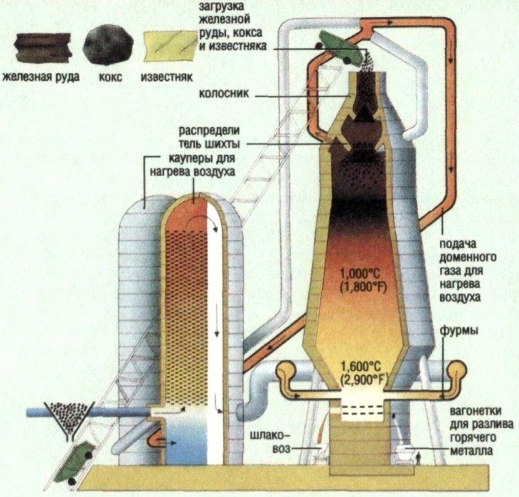
ДОМЕННАЯ ПЕЧЬ — (домна) шахтная печь для выплавки чугуна. Исходные материалы (шихта ) железорудный агломерат, окатыши, кокс, флюсы подаются на колошник. Снизу (через фурмы) вводят нагретый воздух, жидкое, газообразное или пылевидное топливо. В доменной печи… … Большой Энциклопедический словарь
ДОМЕННАЯ ПЕЧЬ — (домна) шахтная печь для выплавки чугуна из железной руды … Большая политехническая энциклопедия
доменная печь — — [http://www.eionet.europa.eu/gemet/alphabetic?langcode=en] EN blast furnace A tall, cylindrical smelting furnace for reducing iron ore to pig iron; the blast of air blown through solid fuel increases the combustion rate. (Source: MGH)… … Справочник технического переводчика
Доменная печь — У этого термина существуют и другие значения, см. Домна (значения). Устройство доменной печи 1. Горячее дутьё 2. Зона плавления (заплечики и горн) 3. Зона восстановления FeO (распар) 4. Зона восстанов … Википедия
доменная печь — (домна), шахтная печь для выплавки чугуна. Исходные материалы (шихта) железорудный агломерат, окатыши, кокс, флюсы подаются на колошник. Снизу (через фурмы) вводят нагретый воздух, жидкое, газообразное или пылевидное топливо. В доменной печи… … Энциклопедический словарь
ДОМЕННАЯ ПЕЧЬ — домна, шахтная печь для выплавки чугуна из железорудных материалов (см. рис.). Печь установлена на бетонном фундаменте, на к ром (в цилиндрич. кожухе) уложена кладка из огнеупорного кирпича, образующая лещадь печи. В нижней части печи горне… … Большой энциклопедический политехнический словарь
Доменная печь — Blast furnace Доменная печь. Шахтная печь, в которой сжигается твердое топливо с подачей воздуха для расплавления руды в течение длительного времени. Так как при производстве чугуна температура должна быть высокой, то воздух подогревают. Там, где … Словарь металлургических терминов
доменная печь — aukštakrosnė statusas T sritis chemija apibrėžtis Ketaus lydymo iš rūdos krosnis. atitikmenys: angl. blast furnace rus. доменная печь; домна … Chemijos terminų aiškinamasis žodynas
доменная печь — [blast furnace] шахтная печь для выплавки чугуна из железных руд или окускованных железорудных концентратов в непрерывно действующем реакторе в противотоке опускающихся шихтовых материалов и восходящего потока горячих восстановительных газов… … Энциклопедический словарь по металлургии
Доменная печь — домна шахтная печь для выплавки чугуна из железной руды. Печь устанавливают на бетонный фундамент, на котором (в цилиндрическом кожухе) делают кладку из огнеупорного кирпича, образующую лещадь печи. В нижней части печи горне имеются чугунные и… … Энциклопедический словарь по металлургии
Источник
Доменная печь


До́менная печь, до́мна — большая металлургическая, вертикально расположенная плавильная печь шахтного типа для выплавки чугуна и ферросплавов из железорудного сырья. Важнейшей особенностью доменного процесса является его непрерывность в течение всей кампании печи (от строительства печи до её капитального ремонта) и противоток поднимающихся вверх фурменных газов с непрерывно опускающимся и наращиваемым сверху новыми порциями шихты столбом материалов.
Первые доменные печи появились в Европе в середине XIV века, в России — около 1630 г.
Содержание
Этимология
Слово «домна» образовано от старославянского «дмение» — дутьё. На других языках: англ. blast furnace — дутьевая печь, нем. Hochofen — высокая печь, фр. haut fourneau — высокая печь.
Следует иметь в виду коренное отличие в значении слов «домница» и «доменная печь»: в домнице получали (в виде кусков или криц) штуки восстановленного сыродутного (от слова «сырое», то есть неподогретое дутьё) железа, а в доменной печи — жидкий чугун.
Описание и процеcсы
Доменная печь представляет собой непрерывно действующий аппарат шахтного типа. Загрузка шихты осуществляется сверху, через типовое загрузочное устройство, которое одновременно является и газовым затвором доменной печи. В домне восстанавливают богатую железную руду (на современном этапе запасы богатой железной руды сохранились лишь в Австралии и Бразилии), агломерат или окатыши. Иногда в качестве рудного сырья используют брикеты.
Доменная печь состоит из пяти конструктивных элементов: верхней цилиндрической части — колошника, необходимого для загрузки и эффективного распределения шихты в печи; самой большой по высоте расширяющейся конической части — шахты, в которой происходят процессы нагрева материалов и восстановления железа из оксидов; самой широкой цилиндрической части — распара, в котором происходят процессы размягчения и плавления восстановленного железа; суживающейся конической части — заплечиков, где образуется восстановительный газ — монооксид углерода; цилиндрической части — горна, служащего для накопления жидких продуктов доменного процесса — чугуна и шлака.
В верхней части горна располагаются фурмы — отверстия для подачи нагретого до высокой температуры дутья — сжатого воздуха, обогащенного кислородом и углеводородным топливом.
На уровне фурм развивается температура около 2000 °C. По мере удаления вверх температура снижается, и у колошников доходит до 270 °C. Таким образом в печи на разной высоте устанавливается разная температура, благодаря чему протекают различные химические процессы перехода руды в металл.

В верхней части горна, где приток кислорода достаточно велик, кокс сгорает, образуя диоксид углерода и выделяя большое количество тепла.


Диоксид углерода, покидая зону, обогащённую кислородом, вступает в реакцию с коксом и образует монооксид углерода — главный восстановитель доменного процесса.


Поднимаясь вверх, монооксид углерода взаимодействует с оксидами железа, отнимая у них кислород и восстанавливая до металла:


Полученное в результате реакции железо каплями стекает по раскалённому коксу вниз, насыщаясь углеродом, в результате чего получается сплав, содержащий 2,14 — 6,67 % углерода. Такой сплав называется чугуном. Кроме углерода в него входят небольшая доля кремния и марганца. В количестве десятых долей процента в состав чугуна входят также вредные примеси — сера и фосфор. Кроме чугуна в горне образуется и накапливается шлак, в котором собираются все вредные примеси.
Ранее шлак выпускался через отдельную шлаковую лётку. В настоящее время и чугун, и шлак выпускают через чугунную лётку одновременно. Разделение чугуна и шлака происходит уже вне доменной печи — в жёлобе, при помощи разделительной плиты. Отделённый от шлака чугун поступает в чугуновозные ковши, либо в ковши миксерного типа.
Фундамент печи
Современная печь вместе со всеми сооружениями и металлоконструкциями, футеровкой (огнеупорной кладкой) и находящимися в ней шихтовыми материалами и продуктами плавки может иметь массу свыше 30 тыс. т. Эта масса должна быть равномерно передана грунту. Нижнюю часть фундамента (подошву) делают в виде массивной бетонной плиты толщиной до 4 м. На подошву опираются колонны, поддерживающие металлические конструкции печи (кожух). Верхняя часть фундамента (пень) представляет собой монолитный цилиндр из жароупорного бетона, на котором находится горн печи.
Горн доменной печи
Горн доменной печи — нижняя часть доменной печи, цилиндрическая по внутреннему очертанию и коническая (иногда цилиндрическая) по наружной форме. Горн оснащен устройствами для выпуска чугуна и шлака (чугунными и шлаковыми летками) и приборами (фурмами) для вдувания нагретого (на кауперах) до 1100—1400 °С, обогащенного кислородом до 23—25 %, воздуха. Горн доменной печи — наиболее ответственная часть её конструкции. Здесь скапливается до 1000 т. и больше расплавленных продуктов плавки — чугуна и шлака. На дно горна оказывает давление весь столб шихты массой 9—12 тыс. т. Давление горновых газов составляет 0,4—0,5 МПа, а их температура в очагах горения кокса достигает 1700—2100 °С. Внутри горна непрерывно движутся и обновляются кокс, жидкие чугун и шлак, горновые газы. По сути это мощный непрерывно движущийся реактор. В связи с этим к конструкциям горна предъявляются жесткие требования по прочности, герметичности и огнеупорности. Основные конструктивные элементы горна — кожух, холодильники, чугунная и шлаковая летка, фурменные приборы.
Чугунная лётка
Это канал прямоугольной формы шириной 250—300 мм с высотой 450—500 мм. Канал делают в огнеупорной кладке горна на высоте 600—1700 мм от поверхности лещади. Каналы для шлаковых лёток выкладывают на высоте 2000—3600 мм. Канал чугунной летки закрыт огнеупорной массой. Открывают чугунную лётку путём высверливания бурильной машиной отверстия диаметром 50—60 мм. После выпуска чугуна и шлака (на современных больших доменных печах выпуск чугуна и шлака осуществляется через чугунные лётки) отверстия забивают с помощью электрической пушки. Носок пушки входит и в неё из пушки под давлением подают лёточную огнеупорную массу. Шлаковая лётка на доменной печи защищена водоохлаждаемыми элементами, которые в совокупности называют шлаковыми стопорами и рычажной конструкции с пневматическим приводом, управляемым дистанционно. Доменные печи большого объёма (3200—5500 м³) оборудованы четырьмя чугунными лётками, работающими попеременно, и одной шлаковой лёткой. Выпуск чугуна и шлака из доменной печи включает в себя следующие операции:
Источник
доменная печь
Смотреть что такое «доменная печь» в других словарях:
ДОМЕННАЯ ПЕЧЬ — ДОМЕННАЯ ПЕЧЬ, цилиндрическая плавильная печь. Ее используют для выплавки из руд металлов, преимущественно железа и меди. Руда смешивается с коксом и Флюсом (при выплавке стали это известняк). К нижней части печи подведен трубопровод горячего… … Научно-технический энциклопедический словарь
ДОМЕННАЯ ПЕЧЬ — (домна) шахтная печь для выплавки чугуна. Исходные материалы (шихта ) железорудный агломерат, окатыши, кокс, флюсы подаются на колошник. Снизу (через фурмы) вводят нагретый воздух, жидкое, газообразное или пылевидное топливо. В доменной печи… … Большой Энциклопедический словарь
ДОМЕННАЯ ПЕЧЬ — (домна) шахтная печь для выплавки чугуна из железной руды … Большая политехническая энциклопедия
доменная печь — — [http://www.eionet.europa.eu/gemet/alphabetic?langcode=en] EN blast furnace A tall, cylindrical smelting furnace for reducing iron ore to pig iron; the blast of air blown through solid fuel increases the combustion rate. (Source: MGH)… … Справочник технического переводчика
Доменная печь — У этого термина существуют и другие значения, см. Домна (значения). Устройство доменной печи 1. Горячее дутьё 2. Зона плавления (заплечики и горн) 3. Зона восстановления FeO (распар) 4. Зона восстанов … Википедия
ДОМЕННАЯ ПЕЧЬ — домна, шахтная печь для выплавки чугуна из железорудных материалов (см. рис.). Печь установлена на бетонном фундаменте, на к ром (в цилиндрич. кожухе) уложена кладка из огнеупорного кирпича, образующая лещадь печи. В нижней части печи горне… … Большой энциклопедический политехнический словарь
Доменная печь — Blast furnace Доменная печь. Шахтная печь, в которой сжигается твердое топливо с подачей воздуха для расплавления руды в течение длительного времени. Так как при производстве чугуна температура должна быть высокой, то воздух подогревают. Там, где … Словарь металлургических терминов
доменная печь — aukštakrosnė statusas T sritis chemija apibrėžtis Ketaus lydymo iš rūdos krosnis. atitikmenys: angl. blast furnace rus. доменная печь; домна … Chemijos terminų aiškinamasis žodynas
доменная печь — [blast furnace] шахтная печь для выплавки чугуна из железных руд или окускованных железорудных концентратов в непрерывно действующем реакторе в противотоке опускающихся шихтовых материалов и восходящего потока горячих восстановительных газов… … Энциклопедический словарь по металлургии
Доменная печь — домна шахтная печь для выплавки чугуна из железной руды. Печь устанавливают на бетонный фундамент, на котором (в цилиндрическом кожухе) делают кладку из огнеупорного кирпича, образующую лещадь печи. В нижней части печи горне имеются чугунные и… … Энциклопедический словарь по металлургии
Источник
Доменная печь
Доменная печь является мощным и высокопроизводительным агрегатом, в котором расходуется огромное количество шихты и дутья. Современная, наибольшая по размерам, доменная печь ежесуточно расходует около 23000 т шихты, 18000 т дутья, 1700 т природного газа и выдает 12000 т чугуна, 4000 т шлака и 27000 т колошникового газа. Таким образом, в большой доменной печи ежеминутно выплавляется около 9 т чугуна. Для обеспечения непрерывной подачи и выпуска столь большого количества материалов необходимо, чтобы конструкции печи были просты и очень надежны.
Общее описание доменной печи
Доменная печь – печь шахтного типа (рис. 19). Сверху в печь порциями непрерывно загружают шихтовые материалы – агломерат (окатыши) и кокс, которые медленно опускаются вниз; длительность их пребывания в печи составляет 4…6 ч. В нижнюю часть печи (верх горна) через фурмы подают дутье – нагретый воздух; у фурм за счет кислорода дутья сгорает кокс с выделением тепла, а горячие продукты сгорания движутся через столб шихты вверх, нагревая ее; время пребывания газов в печи составляет 3…12 с.
 Рис. 19. Общий вид доменной печи с двухконусным засыпным аппаратом:
1 — фундамент; 2 — колонна; 3— летка для выпуска чугуна; 4— чугунные желоба; 5 — фурменные устройства; б — кольцевой воздухопровод; 7 — мараторное кольцо кожуха; 8 — футеровка; 9 — стальной кожух; 10 — колошник; 11 — большой конус; 12 — малый конус; 13 — вращающий механизм засыпного устройства; 14 — приемная воронка; 15, 19 — газоотводы; 16 — скип; 17 — воронка; 18 — наклонный мост; 20 — воронка (чаша); 21 —летка для выпуска шлака; 22 — площадка.
При опускании нагревающейся шихты в ней из оксидов восстанавливается железо, которое науглероживается, расплавляется и каплями стекает в горн, формируя чугун, а невосстановившиеся оксиды в нижней части печи (низ шахты, распар) расплавляются, образуя шлак, который также стекает в горн. Накапливающиеся в горне чугун и шлак, имеющие температуру 1450…1500°С, периодически выпускают через чугунные и шлаковые летки.
Общий вид доменной печи, оборудованной двухконусным засыпным аппаратом, показан на рис. 19. Печь опирается на фундамент 1, большая часть которого заглублена в землю. Снаружи печь заключена в сплошной стальной кожух 9. Внутри кожуха находится футеровка 8, охлаждаемая холодильниками, которые крепятся к внутренней поверхности кожуха. В нижней части печи (горне) расположены летки 3 для выпуска чугуна и летки 21 для выпуска шлака.
Вокруг печи проложен кольцевой футерованный воздухопровод 6, в который из воздухонагревателей подается горячее дутье (воздух); кольцевой воздухопровод служит для подвода дутья к многочисленным расположенным по окружности печи фурменным устройствам 5, через которые дутье поступает в верхнюю часть горна.
Выше колошника 10 печи расположено колошниковое устройство. Оно включает газоотводы 15, 19, служащие для отвода из печи доменного газа; засыпной (загрузочный) аппарат и ряд других механизмов, связанных ci загрузкой шихты и отводом газа. Показаны элементы засыпного аппарата: большой конус 11, закрывающий воронку (чашу) 20; малый конус 12, закрывающий воронку 17, и механизм 13, обеспечивающий их вращение; приемная воронка 14, в которую шихтовые материалы высыпают из скипа 16 путем его опрокидывания, причем скип доставляют на колошник по рельсам наклонного моста 18.
Тяжесть кожуха и футеровки верхней части печи передается на фундамент через мараторное кольцо 7 кожуха и колонны 2. Выпускаемый из печи через летки 3 жидкий чугун поступает в располагаемые на рабочей площадке 22 чугунные желоба 4 и по ним в чугуновозные ковши; выпускаемый через летки 21 шлак по расположенным на площадке 22 шлаковым желобам стекает в шлаковозные ковши либо на установки припечной грануляции жидкого шлака.
Профиль печи
Профилем доменной печи называют очертание рабочего пространства, ограниченного футеровкой. В горизонтальных (поперечных) сечениях профиль представляет собой окружности переменного диаметра.
Профиль печи в вертикальном осевом сечении представлен на рис. 20; основные элементы профиля – это горн, заплечики, распар, шахта и колошник, составляющие полезный объем печи, т.е. объем от оси чугунной летки – О.Ч.Л. – до низа подвижных элементов засыпного аппарата в опущенном положении (в полезный объем не входят объем 1 нижней части горна от оси чугунной летки до кладки лещади, где находится несливаемый слой жидкого чугуна, и ограниченный куполом 3 печи объем 2, в котором расположены элементы засыпного аппарата).
 Рис. 20. Профиль доменной печи
Колошник имеет форму цилиндра и служит для приема загружаемой сверху шихты. Ниже колошника расположена расширяющаяся книзу шахта; это расширение необходимо, чтобы обеспечить свободное опускание шихтовых материалов, объем которых увеличивается в результате нагрева. Распар, представляющий собой короткий цилиндр, служит для создания плавного перехода от расширяющейся шахты к сужающимся заплечикам.
Заплечики выполнены в виде усеченного конуса; такая их форма необходима, поскольку здесь происходит плавление рудной части шихты, в результате чего объем шихты уменьшается и суживающиеся заплечики не позволяют шихте слишком быстро опускаться в горн. Последний имеет цилиндрическую форму, в нижней его части скапливаются жидкие чугун и шлак, а в верхнюю подают дутье и здесь сгорает топливо (кокс).
Основным размером доменной печи является полезный объем. В России доменные печи строятся по типовым проектам, в соответствии с которыми предусмотрены следующие величины полезного объема, м 3 : 1033, 1386, 1513, 1719, 2002, 2300, 2700, 3000, 3200, 4500, 5000 и 5500.
Фундамент, кожух и холодильники
Фундамент состоит из двух частей (рис. 21): нижней, подземной, называемой подошвой 1, и верхней, называемой пнем 2. Подошву выполняют из бетона, а пень – из жароупорного бетона с огнеупорностью 1400…1500 °С. Жаропрочность придается бетону применением огнеупорного наполнителя – боя шамота. В качестве связки применяют портландцемент с тонкомолотыми добавками шамота или огнеупорной глины.
 Рис. 21. Фундамент и лещадь печи объемом 5500 м 3 : 1 — подошва фундамента; 2 — пень; 3 — углеродистые блоки; 4 — холодильники; 5 — воздушное охлаждение низа лещади
Подошву делают в виде восьмиугольной плиты толщиной 4…6 м, толщина пня составляет 2…3,5 м. От перегрева и термического разрушения фундамент на современных печах предохраняют путем воздушного охлаждения низа лещади (стыка лещади с пнем).
На подошву фундамента у большинства печей опираются стальные колонны (рис.19, 2), передающие нагрузку верхнего строения печи.
Кожух доменной печи представляет собой сварную конструкцию, состоящую из цилиндрических и конических поясов, изготовленных из стального листа. Толщина кожуха в верхней части составляет 20…40, в нижней 40…60 мм. Делают кожух из сталей с высокой ударной вязкостью, прочностью, пластичностью, термостойкостью (16Г2АФ, 10Г2С1, 14Г2 и др.).
Большая часть печей имеет кожух с маратором или мараторным кольцом (рис.19, 7), т.е. горизонтально расположенным кольцом из стального листа, сваренным с кожухом нижней части шахты и верха заплечиков. Через маратор и колонны (рис. 19, 2) нагрузка верхней части печи передается на фундамент; кроме того маратор служит опорой для кладки шахты и распара.
В кожухе печи делают вырезы для фурм, чугунных и шлаковых леток, для горизонтальных холодильников (если они имеются), а также отверстия для болтов крепления вертикальных холодильников и для трубок, подводящим к ним воду.
Холодильники служат для охлаждения футеровки и кожуха печи с помощью пропускаемой через них холодной технической воды, а при испарительном охлаждении – с помощью кипящей химически очищенной воды. Широко применяются плитовые холодильники, располагаемые вертикально между кожухом и футеровкой. Холодильник – это плита из чугуна с залитой в ней стальной трубкой в виде змеевика для циркулирующей воды. Холодильник крепят к кожуху печи с помощью болтов.
При испарительном охлаждении во избежание образования паровых пробок кипящая вода должна двигаться снизу вверх; поэтому в плиту заливают две или более вертикально располагаемые трубки с подводом воды к каждой из них снизу и отводом сверху.
Футеровка печи
Огнеупорная футеровка (кладка) доменной печи предназначена для уменьшения тепловых потерь и предохранения кожуха от воздействия высоких температур и от контакта с жидким металлом и шлаком.
Применяемые огнеупоры. Для футеровки доменной печи применяют качественный (доменный) шамотный кирпич, высокоглиноземистый кирпич, углеродистые блоки, иногда карбидокремниевый кирпич. Основу шамота составляют SiО2 и Аl2O3.
Для доменных печей стандартом предусмотрено три сорта шамотных изделий с содержанием Аl2O3 соответственно не менее 42, 41 и 39%; они отличаются повышенной плотностью и прочностью, высокой огнеупорностью (> 1750 °С), низким содержанием Fe2O3 (
Кирпич с более высоким содержанием Аl2O3 применяют для кладки низа печи, а с более низким – для кладки верха. Кроме того, для кладки печей объемом ≤1033 м 3 стандартом предусмотрена марка шамота с меньшим (> 37 %) содержанием Аl2O3, меньшей огнеупорностью (> 1730°С), прочностью и плотностью. Кирпич может быть длиной 230 мм (нормальный) и 345 мм (полуторный). Применение кирпичей различной длины обеспечивает хорошее переплетение швов кладки.
Высокоглиноземистый муллитовый кирпич, применяемый для кладки лещади, содержит > 63 % Аl2O3 при огнеупорности >1800 °С. Доменный карбидокремниевый кирпич содержит > 72 % SiC и > 7 % азота и отличается от огнеупоров на основе Аl2O3 и SiO2 заметно большей прочностью и теплопроводностью.
Углеродистые блоки изготовляют из кокса и обожженного антрацита с добавкой в качестве связующего небольшого количества каменноугольного пека. Длина блоков достигает 3…4 м, они прямоугольного сечения 400×400 и 550×550 мм. Блоки в комбинации с высокоглиноземистым кирпичом больших размеров (400×200×100 мм) применяют для кладки самой нижней части печи – лещади.
Швы между огнеупорными кирпичами заполняют раствором, изготовленным из мертелей, соответствующих классу кирпича. Мертель – это порошок, состоящий из измельченного шамота и огнеупорной глины. Для ответственных видов кладки применяют мертели с добавкой небольших количеств поверхностно-активных и клеющих веществ (сода, сульфитно-спиртовая барда), что позволяет приготавливать растворы с меньшей влажностью при одновременном повышении их пластичности.
Для заполнения швов между углеродистыми блоками применяют углеродистую пасту, состоящую из кокса и смолопека. Зазор между блоками допускается не более 0,5 мм для вертикальных и не более 1,5 мм для горизонтальных швов.
Лещадь. Ранее лещади доменных печей выкладывали из качественного шамотного кирпича. Однако рост объема печей и интенсификация плавки вызывали быстрое разрушение такой кладки. Поэтому в настоящее время лещади делают либо цельноуглеродистыми, либо комбинированными из углеродистых и высокоглиноземистых огнеупоров. Применение углеродистых огнеупоров вызвано тем, что из-за их высокой теплопроводности снижается перегрев и вследствие этого уменьшается разрушение кладки лещади.
Горн. Футеровку горна до уровня фурм выполняют из углеродистых блоков, а в районах фурм и чугунных и шлаковых леток из шамотного (> 42 % Аl2O3) кирпича, поскольку углерод здесь может окисляться кислородом дутья, диоксидом углерода (СO2), а также парами воды из огнеупорных масс. При работе на безводных леточных массах район чугунных леток делают из углеродистых блоков. Для предотвращения окисления углеродистых блоков в период задувки печи их защищают кладкой в один ряд из шамотного кирпича.
Толщина футеровки у низа горна достигает 1600 мм. Снаружи кладку горна охлаждают гладкими плитовыми холодильниками.
Заплечики. Кладку заплечиков чаще всего делают тонкостенной (толщина 230 или 345 мм) из шамотного (> 42 % Аl2O3) кирпича в один ряд, при этом кирпич примыкает к периферийным плитовым холодильникам с залитым кирпичом. Иногда вместо шамота применяют карбидокремние вые кирпичи. Кладка заплечиков быстро изнашивается и вместо нее на поверхности холодильников формируется слой гарнисажа (застывшего шлака и мелких кусков шихты).
Шахта и распар. Кладку распара и охлаждаемой части шахты (
2/3 ее высоты снизу) выполняют из шамотного (> 41…42 % Аl2O3) или карбидокремниевого кирпича, а кладку верхней неохлаждаемой части шахты из шамота, содержащего > 39 % Аl2O3. Кирпичи укладывают в два – три ряда вперевязку.
Кладка шахты с распаром может быть толсто-, средне- и тонкостенной. В прежние годы широко применяли толстостенную кладку (толщина верха шахты 800…900 мм и до 1300 мм в районе распара) с горизонтальными холодильниками, заглубленными в кладку и служащими ее опорой. Однако в связи с тем, что холодильники расположены на расстоянии друг от друга, плохо охлаждается кожух, и после износа футеровки возникают его местные перегревы, вызывая термическую деформацию и возможность появления трещин.
Кроме того, вырезы в кожухе для установки горизонтальных холодильников снижают его прочность и делают кожух менее герметичным. В связи с этим в последние годы делают тонко- и среднестенные шахты. Тонкостенная шахта (и распар) имеет в охлаждаемой части толщину кладки 230…345 мм и в верхней неохлаждаемой части 575…690 мм с охлаждением вертикальными ребристыми холодильниками, причем часть холодильников имеет горизонтальные выступы, которые служат опорой для кладки и способствуют удержанию гарнисажа.
Среднестенная шахта имеет толщину кладки в охлаждаемой части 575…900 мм и в неохлаждаемой 700 мм, охлаждение либо комбинированное из вертикальных ребристых холодильников в сочетании с горизонтальными, либо из вертикальных ребристых холодильников, имеющих горизонтальные выступы.
В распаре и охлаждаемой части шахты по мере износа кирпича образуется слой гарнисажа. С тем, чтобы уменьшить давление от расширяющейся при нагреве кладки на кожух печи и предотвратить его разрыв, между футеровкой и вертикальными холодильниками по всей высоте печи (кроме распара) предусматривают зазор в 70…200 мм, заполняемый шамотоасбестовой или пластичной углеродистой массой.
Колошник. Собственно футеровка колошника состоит из одного ряда шамотного кирпича, выкладываемого у кожуха. За ним располагают “колошниковую защиту”, которая воспринимает удары падающих сверху в процессе загрузки кусков шихты. Широко распространенная ее разновидность состоит из стальных сегментов – литых полых коробок, заполненных шамотным кирпичом. Сегменты расположены несколькими кольцевыми рядами по высоте колошника; соседние по окружности сегменты соединены между собой болтами.
Вся колошниковая защита крепится к кожуху с помощью не скольких подвесок, в каждой из которых сегменты прикреплены к вертикальной пластине, соединенной с серьгой, которая свободно подвешена на штыре, вставленном в отверстие кронштейна; последний прикреплен к кожуху болтами. Такая подвеска позволяет всем сегментам перемещаться вверх в случае роста кладки шахты в вертикальном направлении в результате ее нагрева.
Горн доменной печи
Горн условно подразделяют на две части – верхнюю фурменную зону, где сгорает кокс, и нижнюю – металлоприемник, служащий для накопления жидкого чугуна и шлака, и где расположены чугунные и шлаковые летки. Высота горна (расстояние от оси чугунной летки до заплечиков) на современных печах составляет 3,2…3,9 м, а на наиболее мощной отечественной печи объемом 5500 м 3 она увеличена до 5,7 м.
Чугунные летки располагают на 600…1800 мм выше лещади, а находящаяся ниже леток часть металлоприемника заполнена несливаемым или “мертвым” слоем жидкого чугуна; этот слой необходим для предотвращения размывания лещади потоками чугуна в горне и предохранения ее от воздействия высоких температур. Печи малого объема имеют одну чугунную летку, печи объемом около 2000 м 3 – две, печи объемом 2700 м 3 – три, а печи объемом 3200…5500 м 3 – четыре летки.
На больших печах с четырьмя поочередно работающими летками, число выпусков чугуна в сутки достигает 18…24, на печи объемом 1000 м 3 оно равно 4…5.
Чугунная летка показана на рис. 22. Вырез для летки в кожухе печи обрамлен приваренной к нему стальной кольцевой рамой 2, футерованной внутри шамотным кирпичом. Летка представляет собой сквозной канал в кладке горна и рамы; этот канал шириной 250…300 и высотой 400…500 мм заполнен огнеупорной леточной массой. Для выпуска чугуна в массе просверливают отверстие диаметром 50…80 мм с помощью сверлильной машины, вращающей бур. После выпуска чугуна канал летки забивают огнеупорной массой с помощью электропушки.
 Рис. 22. Чугунная летка:
1 — кожух печи; 2 — рама летки; 3 — шамотная кладка; 4 — холодильник летки; 5 — леточная масса; 6 — канал летки; 7 — жидкий чугун
Шлаковые летки обрамляют арматурой, называемой шлаковым прибором, который помещают в проем горновых холодильников и крепят к кожуху печи. Шлаковый прибор преставлен на рис. 23.
 Рис. 23. Шлаковый прибор
Он состоит из телескопически соединенных элементов: медной сварной или штампованной полой охлаждаемой водой фурмы 1 диаметром 50…70 мм, литого медного полого холодильника (шлаковой амбразуры) 2, чугунного холодильника 3 с залитым спиральным змеевиком для охлаждающей воды, чугунной водоохлаждаемой амбразуры 4 аналогичной конструкции и рамы 5, при помощи которой прибор крепится к кожуху печи.
Все элементы прибора имеют коническую форму, что облегчает их замену при повреждении. Отверстие шлаковой фурмы закрывают металлической пробкой при помощи специального механического стопора. Конусную полость шлакового прибора набивают огнеупорной массой, в которой прорезают отверстие для выхода шлака из печи. Трубки 6 служат для подвода…отвода воды к фурме.
Фурменный прибор. В верхней части горна на расстоянии 2700…3500 мм от оси чугунной летки горна по его окружности с равными промежутками устанавливают воздушные фурмы, через которые в печь поступает нагретое до 1100…1300 °С дутье, природный газ и другие топливные добавки (мазут, пылеугольное топливо).
На существующих печах объемом от 1033 до 5500 м 3 число фурм составляет 16…42).
Комплекс устройств, служащих для подвода дутья в горн из кольцевого воздухопровода, называют фурменным прибором (рис. 24).
 Рис. 24. Фурменный прибор
Основная часть прибора – медная пустотелая воздушная фурма 1 с внутренним диаметром 140…190 мм, охлаждаемая водой. Фурма выступает из кладки внутрь печи на расстояние 300…500 мм.
Фурму устанавливают в медную полую литую амбразуру 2, а амбразуру – в имеющий залитую спиральную трубку чугунный холодильник (кадушку) 3, который своим фланцем крепится к кожуху печи с помощью болтов. Фурма, амбразура и холодильник охлаждаются проточной водой.
Дутье, подаваемое к фурме 1 из кольцевого воздухопровода 12, проходит по прикрепленным к нему рукаву 11 и неподвижному патрубку (колену) 10; подвижному колену 7, которое прикреплено к патрубку 10 при помощи двух подвесок 8, и по сменному соплу 4. Подвижное колено 7 прижимает сопло к фурме с помощью пружинного натяжного устройства 5, присоединенного к кожуху печи.
Для обеспечения герметичности прибора (на случай перекосов отдельных элементов в результате нагрева и др.) в местах стыка фурма-сопло, сопло-подвижное колено и подвижное колено-патрубок 10 предусмотрены шаровые соединения (стыки заточены по шаровой поверхности). В торце подвижного колена предусмотрена закрытая стеклом гляделка 6 для наблюдения за работой прифурменной зоны.
Рукав, патрубок 10 и подвижное колено футеруют внутри шамотным кирпичом. Сопло делают из стали с тонкой футеровкой изнутри.
Фурма и амбразура периодически прогорают и для их смены отсоединяют натяжное устройство 5, ослабляют подвески 8 и разворачивают подвижное колено вокруг оси 9 подвесок 8 в положение, удобное для удаления сопла, фурмы и амбразуры.
Кольцевой воздухопровод 12, по которому горячее дутье подводят к фурмам, футерован шамотным кирпичом и имеет диаметр в свету 800…1800 мм в зависимости от объема печи.
Колошниковое устройство
Колошниковое устройство представляет собой многоэтажную металлическую конструкцию, служащую для поддержания комплекса механизмов, предназначенных для загрузки шихты в доменную печи (засыпной аппарат и др.), отвода газов (газоотводы) и для монтажа оборудования.
Газоотводы. Для отвода доменного газа в куполе печи имеются отверстия и идущие от них вверх газоотводы. Обычно число газоотводов равно четырем, их соединяют вначале симметрично попарно, а затем в один газоход, идущий вниз к пылеуловителям, расположенным на нулевой отметке (на печах объемом 5000…5500 м 3 имеется восемь газоотводов и по два нисходящих газохода). От верхних точек газоотводов отходят вертикальные свечи (трубы), заканчивающиеся атмосферным клапаном, который открывается, выпуская газ в атмосферу при превышении давления в печи сверх допустимого. Число свечей с клапанами колеблется от двух до четырех, они служат также для выпуска газа при остановках печи.
Засыпной аппарат. Он предназначен для загрузки шихты, необходимого ее распределения по сечению колошника, т.е. печи и для обеспечения герметичности печи в процессе загрузки, т.е. для предотвращения попадания в печь воздуха, ведущего к возможности взрыва, и предотвращения выделения печного газа в атмосферу.
Большая часть доменных печей оборудована двухконусными засыпными аппаратами, а новые печи сооружают с засыпными аппаратами новой конструкции – бесконусными.
Двухконусный засыпной аппарат показан на рис. 25, а.
Его основными элементами являются:
Большой и малый конусы могут перемещаться вверх-вниз; в верхнем положении большой конус прижат к воронке 2, а малый к воронке 10, изолируя рабочее пространство печи от атмосферы; положение конусов в опущенном состоянии показано пунктиром. Малый конус подвешен на полой трубчатой штанге 5, большой – на штанге 3, проходящей внутри полой штанги 5, благодаря чему конусы могут опускаться и подниматься независимо друг от друга. Воронка 10 связана с приводом, обеспечивающим ее вращение вместе с малым конусом.
Шихтовые материалы доставляют на колошник двумя скипами (тележками), движущимися по рельсам 8 наклонного моста 9; в крайнем верхнем положении скип 7 опрокидывается, поскольку его передние колеса катятся по рельсам, загнутым вниз, а задние — по другим рельсам, загнутым вверх и поднимающим заднюю часть скипа (см. рис. 25, а). При этом порция шихты высыпается через приемную воронку на поверхность малого конуса, после чего он опускается и материал просыпается вниз на поверхность большого конуса, а малый конус сразу же поднимается.
Подобным образом на поверхность большого конуса загружают два-шесть скипов (набирают подачу). Затем при поднятом малом конусе опускают большой конус, и материал подачи просыпается в печь, после чего большой конус поднимается.
Далее на большой конус набирают новую подачу (два-шесть скипов), но перед каждым опусканием малого конуса он с воронкой 10 поворачивается на 60°. Загрузив эту подачу в печь путем опускания и подъема большого конуса, на него набирают следующую подачу; при этом перед каждым опусканием малого конуса он с воронкой поворачивается на 120° от исходного положения. При наборе последующей подачи угол поворота составляет 180° и т.д.
Благодаря такому вращению распределителя подачи попадают не в одно место под наклонным мостом 9, а сравнительно равномерно распределяются по периферии колошника.
В процессе загрузки конусы работают поочередно: когда один опущен, другой поднят (закрыт), что обеспечивает герметичность печи.
После опускания малого конуса в межконусном пространстве создается давление, соответствующее атмосферному, а большой конус находится под давлением газов в печи, что препятствует его опусканию. После же опускания большого конуса, в межконусном пространстве создается давление, равное давлению газов в печи, что препятствует открытию малого конуса.
Для выравнивания давления в межконусном пространстве и печи подают чистый газ в межконусное пространство под давлением, близким к давлению газов в печи. Это делают перед опусканием большого конуса при помощи уравнительных клапанов, а при опускании малого конуса сбрасывающий клапан выпускает газ из межконусного пространства в атмосферу. Работа уравнительных клапанов автоматизирована и сблокирована с работой конусов засыпного аппарата.
Слабым местом аппарата являются стыки конусов с соответствующими воронками. Здесь в связи с повышенным давлением в печи просачивается доменный газ и содержащаяся в нем пыль вызывает абразивный износ металла. Поэтому стойкость конусов низкая, малый; конус заменяют почти через каждые полгода, а большой через 1,5…2,5 г.
Среди ряда бесконусных загрузочных устройств хорошо зарекомендовала себя конструкция фирмы “Поль Вюрт” (Люксембург). Схема подобного устройства показана на рис. 25, б.
Его основные элементы:
Шлюзовые бункеры 5 объемом 50…80 м 3 оборудованы верхним 4, нижним 7 газоотсекающими клапанами и шихтовым дозирующим затвором 6. Газоотсекающие клапаны обеспечивают герметичность печи, поскольку верхний клапан открывают при закрытом нижнем и наоборот. Отсечная задвижка 9 служит для герметизации печи при ремонтах загрузочного устройства.
Загрузку шихты производят следующим образом. Приемную воронку 2 устанавливают над пустым бункером 6, открывают верхний газоотсекающий клапан 4 при закрытых нижнем клапане 7 и затворе 6 бункера и, открыв затвор 3 воронки, начинают подачу шихты в бункер с конвейера 1 шихтоподачи; наполнив бункер, закрывают затвор воронки и верхний газоотсекающий клапан.
Для выгрузки шихты в печь открывают нижний газоотсекающий клапан и затем шихтовый затвор 6 бункера, при этом скорость высыпания материала из бункера определяется степенью раскрытия шихтового затвора. Высыпающийся из бункера материал через трубу 8 попадает на вращающийся лоток 11 и скатывается по нему в печь. После опорожнения бункера закрывают шихтовый затвор б и затем нижний газоотсекающий клапан 7. За время опорожнения бункера лоток совершает не менее 10 оборотов, при этом угол наклона лотка изменяют по заданной программе в пределах 7…53°, выгрузка длится 60…140 с.
Правый и левый бункеры 5 работают поочередно: когда наполняют один бункер, из другого материал выгружают в печь. Шихту с конвейера 1 направляют в тот или иной бункер, передвигая приемную воронку 2. Газоуплотнительные клапаны выполняют только функцию уплотнения, не соприкасаясь с шихтой, что увеличивает срок их службы.
При работе загрузочного устройства перед открытием газоотсекающих клапанов производят выравнивание давления в бункерах 5 с давлением в печи или с атмосферным. Чтобы предотвратить выброс из бункеров 5 запыленного доменного газа в атмосферу, на отечественных печах предусмотрена система пылеподавления, заключающаяся в том, что в бункер во время выгрузки из него шихты подают азот под давлением большим, чем давление газов в печи, и поэтому газы из печи в бункер и из него в атмосферу не попадают.
Недостатком устройства считают то, что сложный механизм вращения лотка расположен в куполе печи и для его охлаждения и защиты от горячих колошниковых газов требуется расходовать много (10…30 тыс.м 3 /ч) азота или очищенного охлажденного доменного газа; кроме этого раз в три-четыре месяца необходима кратковременная остановка печи для замены резиновых прокладок газоотсекающих клапанов.
Источники:
Источник
Теперь вы знаете какие однокоренные слова подходят к слову Доменная печь как пишется, а так же какой у него корень, приставка, суффикс и окончание. Вы можете дополнить список однокоренных слов к слову «Доменная печь как пишется», предложив свой вариант в комментариях ниже, а также выразить свое несогласие проведенным с морфемным разбором.
ДОМЕННАЯ ПЕЧЬ
- ДОМЕННАЯ ПЕЧЬ
- ДОМЕННАЯ печь (домна) — шахтная печь для выплавки чугуна. Исходные материалы (шихта ) — железорудный агломерат, окатыши, кокс, флюсы — подаются на колошник. Снизу (через фурмы) вводят нагретый воздух, жидкое, газообразное или пылевидное топливо. В доменной печи происходит восстановление железа из оксидов и насыщение его углеродом. Продукты плавки — чугун и шлак — периодически выпускаются через летки (отверстия) в нижней части доменной печи. Полезный объем наиболее крупной в Российской Федерации доменной печи 5580 м³ (1989). Кампания доменной печи (от задувки до капитального ремонта) ок. 10 лет. Первые доменные печи появились в Европе в сер. 14 в., в России — ок. 1630.
Большой Энциклопедический словарь.
2000.
Смотреть что такое «ДОМЕННАЯ ПЕЧЬ» в других словарях:
-
ДОМЕННАЯ ПЕЧЬ — ДОМЕННАЯ ПЕЧЬ, цилиндрическая плавильная печь. Ее используют для выплавки из руд металлов, преимущественно железа и меди. Руда смешивается с коксом и Флюсом (при выплавке стали это известняк). К нижней части печи подведен трубопровод горячего… … Научно-технический энциклопедический словарь
-
ДОМЕННАЯ ПЕЧЬ — (домна) шахтная печь для выплавки чугуна из железной руды … Большая политехническая энциклопедия
-
доменная печь — — [http://www.eionet.europa.eu/gemet/alphabetic?langcode=en] EN blast furnace A tall, cylindrical smelting furnace for reducing iron ore to pig iron; the blast of air blown through solid fuel increases the combustion rate. (Source: MGH)… … Справочник технического переводчика
-
Доменная печь — У этого термина существуют и другие значения, см. Домна (значения). Устройство доменной печи 1. Горячее дутьё 2. Зона плавления (заплечики и горн) 3. Зона восстановления FeO (распар) 4. Зона восстанов … Википедия
-
доменная печь — (домна), шахтная печь для выплавки чугуна. Исходные материалы (шихта) железорудный агломерат, окатыши, кокс, флюсы подаются на колошник. Снизу (через фурмы) вводят нагретый воздух, жидкое, газообразное или пылевидное топливо. В доменной печи… … Энциклопедический словарь
-
ДОМЕННАЯ ПЕЧЬ — домна, шахтная печь для выплавки чугуна из железорудных материалов (см. рис.). Печь установлена на бетонном фундаменте, на к ром (в цилиндрич. кожухе) уложена кладка из огнеупорного кирпича, образующая лещадь печи. В нижней части печи горне… … Большой энциклопедический политехнический словарь
-
Доменная печь — Blast furnace Доменная печь. Шахтная печь, в которой сжигается твердое топливо с подачей воздуха для расплавления руды в течение длительного времени. Так как при производстве чугуна температура должна быть высокой, то воздух подогревают. Там, где … Словарь металлургических терминов
-
доменная печь — aukštakrosnė statusas T sritis chemija apibrėžtis Ketaus lydymo iš rūdos krosnis. atitikmenys: angl. blast furnace rus. доменная печь; домна … Chemijos terminų aiškinamasis žodynas
-
доменная печь — [blast furnace] шахтная печь для выплавки чугуна из железных руд или окускованных железорудных концентратов в непрерывно действующем реакторе в противотоке опускающихся шихтовых материалов и восходящего потока горячих восстановительных газов… … Энциклопедический словарь по металлургии
-
Доменная печь — домна шахтная печь для выплавки чугуна из железной руды. Печь устанавливают на бетонный фундамент, на котором (в цилиндрическом кожухе) делают кладку из огнеупорного кирпича, образующую лещадь печи. В нижней части печи горне имеются чугунные и… … Энциклопедический словарь по металлургии
Значение словосочетания «доменная печь»

-
Доменная печь — то же, что
домна.См. также доменный.
Источник (печатная версия): Словарь русского языка: В 4-х
т. / РАН,
Ин-т лингвистич.
исследований; Под ред. А. П. Евгеньевой. — 4-е изд., стер. — М.: Рус. яз.;
Полиграфресурсы,
1999;
(электронная версия): Фундаментальная
электронная
библиотека
- До́менная печь, до́мна — большая металлургическая, вертикально расположенная плавильная печь шахтного типа для выплавки чугуна и ферросплавов из железорудного сырья. Важнейшей особенностью доменного процесса является его непрерывность в течение всей кампании печи (от строительства печи до её «капитального» ремонта) и противоток поднимающихся вверх фурменных газов с непрерывно опускающимся и наращиваемым сверху новыми порциями шихты столбом материалов.
Источник: Википедия
-
Доменная печь (тех.)
— то же, что домна.См. также доменный.
Источник: «Толковый словарь русского языка» под редакцией Д. Н. Ушакова (1935-1940);
(электронная версия): Фундаментальная
электронная
библиотека
Делаем Карту слов лучше вместе

Привет! Меня зовут Лампобот, я компьютерная программа, которая помогает делать
Карту слов. Я отлично
умею считать, но пока плохо понимаю, как устроен ваш мир. Помоги мне разобраться!
Спасибо! Я стал чуточку лучше понимать мир эмоций.
Вопрос: тараторящий — это что-то нейтральное, положительное или отрицательное?
Ассоциации к слову «печь»
Синонимы к словосочетанию «доменная печь»
Предложения со словосочетанием «доменная печь»
- Типовые лифты – и грузовые, и пассажирские – обслуживают заводы, доменные печи, нефтепереработки.
- По мере смены эпох на панно сельские пейзажи уступают место паровозам, доменным печам, прочим прелестям промышленной революции и, наконец, гигантским мачтам линий электропередачи, несущих энергию планете.
- Легко представить, что весь этот горячий воздух похож на доменную печь.
- (все предложения)
Цитаты из русской классики со словосочетанием «доменная печь»
- Хозяева — с трудом могут продышать скопившиеся внутри храпы; кучер — от сытости не отличает правую руку от левой; дворник — стоит с метлой у ворот и брюхо об косяк чешет, кухарка — то и дело робят родит, а лошади, раскормленные, словно доменные печи, как угорелые выскакивают из каретного сарая, с полною готовностью вонзить дышло в любую крепостную стену.
- Дальше, за этой природной террасой, глаза разбегались на том хаосе, который представляла собою местность, предназначенная для возведения пятой и шестой доменных печей.
- На фабрике работа шла своим чередом. Попрежнему дымились трубы, попрежнему доменная печь выкидывала по ночам огненные снопы и тучи искр, по-прежнему на плотине в караулке сидел старый коморник Слепень и отдавал часы. Впрочем, он теперь не звонил в свой колокол на поденщину или с поденщины, а за него четыре раза в день гудел свисток паровой машины.
- (все
цитаты из русской классики)
Сочетаемость слова «печь»
- русская печь
микроволновая печь
доменные печи - в печь дров
из печи чугунок
печи крематория - дверца печи
жар печи
топка печей - печь топилась
печи дымили
печь остыла - топить печь
растопить печь
затопить печь - солнце пекло
настоящее пекло - печь пироги
печь хлеб
печь блины - (полная таблица сочетаемости)
Понятия со словосочетанием «доменная печь»
-
До́менная печь, до́мна — большая металлургическая вертикально расположенная печь шахтного типа для выплавки чугуна и ферросплавов из железорудного сырья. Важнейшей особенностью доменного процесса является его непрерывность в течение всей кампании печи (от строительства печи до её капитального ремонта) и противоток поднимающихся вверх фурменных газов с непрерывно опускающимся и наращиваемым сверху новыми порциями шихты столбом материалов.
-
Заду́вка до́менной печи́ — начальная операция в кампании доменной печи (новой печи или печи после капитального ремонта 1-го разряда).
- (все понятия)
Афоризмы русских писателей со словом «печь»
- И из недр обугленной России
Говорю: «Ты прав, что так судил!
Надо до алмазного закала
Прокалить всю толщу бытия,
Если ж дров в плавильной печи мало,
Господи! — вот плоть моя!» - Земля — зола, и вода — смола,
И некуда вроде податься…
Неисповедимы дороги зла,
Но не надо, люди, бояться!
Не бойтесь золы, не бойтесь хулы,
Не бойтесь пекла и ада,
А бойтесь единственно только того,
Кто скажет: «Я знаю, как надо!» - Дети пекут улыбки больших глаз
В жаровнях темных ресниц
И со смехом дают случайным прохожим. - (все афоризмы русских писателей)
Отправить комментарий
Дополнительно

Former blast furnace in Port of Sagunt, Valencia, Spain.
A blast furnace is a type of metallurgical furnace used for smelting to produce industrial metals, generally pig iron, but also others such as lead or copper. Blast refers to the combustion air being «forced» or supplied above atmospheric pressure.[1]
In a blast furnace, fuel (coke), ores, and flux (limestone) are continuously supplied through the top of the furnace, while a hot blast of air (sometimes with oxygen enrichment) is blown into the lower section of the furnace through a series of pipes called tuyeres, so that the chemical reactions take place throughout the furnace as the material falls downward. The end products are usually molten metal and slag phases tapped from the bottom, and waste gases (flue gas) exiting from the top of the furnace.[2] The downward flow of the ore along with the flux in contact with an upflow of hot, carbon monoxide-rich combustion gases is a countercurrent exchange and chemical reaction process.[3]
In contrast, air furnaces (such as reverberatory furnaces) are naturally aspirated, usually by the convection of hot gases in a chimney flue. According to this broad definition, bloomeries for iron, blowing houses for tin, and smelt mills for lead would be classified as blast furnaces. However, the term has usually been limited to those used for smelting iron ore to produce pig iron, an intermediate material used in the production of commercial iron and steel, and the shaft furnaces used in combination with sinter plants in base metals smelting.[4][5]
Blast furnaces are estimated to have been responsible for over 4% of global greenhouse gas emissions between 1900 and 2015, but are difficult to decarbonize.[6]
Process engineering and chemistry[edit]


Charcoal burning iron blast furnace in Ohio, 1923
Blast furnaces operate on the principle of chemical reduction whereby carbon monoxide converts iron oxides to elemental iron. Blast furnaces differ from bloomeries and reverberatory furnaces in that in a blast furnace, flue gas is in direct contact with the ore and iron, allowing carbon monoxide to diffuse into the ore and reduce the iron oxide. The blast furnace operates as a countercurrent exchange process whereas a bloomery does not. Another difference is that bloomeries operate as a batch process whereas blast furnaces operate continuously for long periods. Continuous operation is also preferred because blast furnaces are difficult to start and stop. Also, the carbon in pig iron lowers the melting point below that of steel or pure iron; in contrast, iron does not melt in a bloomery.
Silica has to be removed from the pig iron. It reacts with calcium oxide (burned limestone) and forms silicates, which float to the surface of the molten pig iron as «slag». Historically, to prevent contamination from sulfur, the best quality iron was produced with charcoal.
The downward moving column of ore, flux, coke or charcoal and reaction products must be sufficiently porous for the flue gas to pass through. To ensure this permeability the particle size of the coke or charcoal is of great relevance. Therefore, the coke must be strong enough so it will not be crushed by the weight of the material above it. Besides the physical strength of its particles, the coke must also be low in sulfur, phosphorus, and ash.[7]

Rising carbon monoxide reduces iron oxides to pure iron through a series of reactions that occur at different areas within a blast furnace.
The main chemical reaction producing the molten iron is:
- Fe2O3 + 3CO → 2Fe + 3CO2[8]
This reaction might be divided into multiple steps, with the first being that preheated air blown into the furnace reacts with the carbon in the form of coke to produce carbon monoxide and heat:
- 2 C(s) + O2(g) → 2 CO(g)[9]
The hot carbon monoxide is the reducing agent for the iron ore and reacts with the iron oxide to produce molten iron and carbon dioxide. Depending on the temperature in the different parts of the furnace (warmest at the bottom) the iron is reduced in several steps. At the top, where the temperature usually is in the range between 200 °C and 700 °C, the iron oxide is partially reduced to iron(II,III) oxide, Fe3O4.
- 3 Fe2O3(s) + CO(g) → 2 Fe3O4(s) + CO2(g)[9]
The temperatures 850 °C, further down in the furnace, the iron(II,III) is reduced further to iron(II) oxide:
- Fe3O4(s) + CO(g) → 3 FeO(s) + CO2(g)[9]
Hot carbon dioxide, unreacted carbon monoxide, and nitrogen from the air pass up through the furnace as fresh feed material travels down into the reaction zone. As the material travels downward, the counter-current gases both preheat the feed charge and decompose the limestone to calcium oxide and carbon dioxide:
- CaCO3(s) → CaO(s) + CO2(g)[9]
The calcium oxide formed by decomposition reacts with various acidic impurities in the iron (notably silica), to form a fayalitic slag which is essentially calcium silicate, CaSiO
3:[8]
- SiO2 + CaO → CaSiO3[10][11]
As the iron(II) oxide moves down to the area with higher temperatures, ranging up to 1200 °C degrees, it is reduced further to iron metal:
- FeO(s) + CO(g) → Fe(s) + CO2(g)[9]
The carbon dioxide formed in this process is re-reduced to carbon monoxide by the coke:
- C(s) + CO2(g) → 2 CO(g)[9]
The temperature-dependent equilibrium controlling the gas atmosphere in the furnace is called the Boudouard reaction:
-
- 2CO ⇌ CO2 + C
The «pig iron» produced by the blast furnace has a relatively high carbon content of around 4–5% and usually contains too much sulphur, making it very brittle, and of limited immediate commercial use. Some pig iron is used to make cast iron. The majority of pig iron produced by blast furnaces undergoes further processing to reduce the carbon and sulphur content and produce various grades of steel used for construction materials, automobiles, ships and machinery. Desulphurisation usually takes place during the transport of the liquid steel to the steelworks. This is done by adding calcium oxide, which reacts with the iron sulfide contained in the pig iron to form calcium sulfide (called lime desulfurization).[12] In a further process step, the so-called basic oxygen steelmaking, the carbon is oxidized by blowing oxygen onto the liquid pig iron to form crude steel.
Although the efficiency of blast furnaces is constantly evolving, the chemical process inside the blast furnace remains the same. One of the biggest drawbacks of the blast furnaces is the inevitable carbon dioxide production as iron is reduced from iron oxides by carbon and as of 2016, there is no economical substitute – steelmaking is one of the largest industrial contributors of the CO2 emissions in the world (see greenhouse gases).[13] Several alternatives are being investigated such as plastic waste, biomass or hydrogen as reducing agent, which can substantially reduce the carbon emissions.[14]
The challenge set by the greenhouse gas emissions of the blast furnace is being addressed in an ongoing[when?] European Program called ULCOS (Ultra Low CO2 Steelmaking).[15] Several new process routes have been proposed and investigated in depth to cut specific emissions (CO2 per ton of steel) by at least 50%. Some rely on the capture and further storage (CCS) of CO2, while others choose decarbonizing iron and steel production, by turning to hydrogen, electricity and biomass.[16] In the nearer term, a technology that incorporates CCS into the blast furnace process itself and is called the Top-Gas Recycling Blast Furnace is under development, with a scale-up to a commercial size blast furnace under way.[needs update]
History[edit]


Cast iron has been found in China dating to the 5th century BC, but the earliest extant blast furnaces in China date to the 1st century AD and in the West from the High Middle Ages.[17] They spread from the region around Namur in Wallonia (Belgium) in the late 15th century, being introduced to England in 1491. The fuel used in these was invariably charcoal. The successful substitution of coke for charcoal is widely attributed to English inventor Abraham Darby in 1709. The efficiency of the process was further enhanced by the practice of preheating the combustion air (hot blast), patented by Scottish inventor James Beaumont Neilson in 1828.[18]
China[edit]
Archaeological evidence shows that bloomeries appeared in China around 800 BC. Originally it was thought that the Chinese started casting iron right from the beginning, but this theory has since been debunked[clarification needed] by the discovery of ‘more than ten’ iron digging implements found in the tomb of Duke Jing of Qin (d. 537 BC), whose tomb is located in Fengxiang County, Shaanxi (a museum exists on the site today).[19] There is however no evidence of the bloomery in China after the appearance of the blast furnace and cast iron. In China, blast furnaces produced cast iron, which was then either converted into finished implements in a cupola furnace, or turned into wrought iron in a fining hearth.[20]
Although cast iron farm tools and weapons were widespread in China by the 5th century BC, employing workforces of over 200 men in iron smelters from the 3rd century onward, the earliest blast furnaces constructed were attributed to the Han Dynasty in the 1st century AD.[21] These early furnaces had clay walls and used phosphorus-containing minerals as a flux.[22] Chinese blast furnaces ranged from around two to ten meters in height, depending on the region. The largest ones were found in modern Sichuan and Guangdong, while the ‘dwarf» blast furnaces were found in Dabieshan. In construction, they are both around the same level of technological sophistication [23]
The effectiveness of the Chinese human and horse powered blast furnaces was enhanced during this period by the engineer Du Shi (c. AD 31), who applied the power of waterwheels to piston-bellows in forging cast iron.[24] Early water-driven reciprocators for operating blast furnaces were built according to the structure of horse powered reciprocators that already existed. That is, the circular motion of the wheel, be it horse driven or water driven, was transferred by the combination of a belt drive, a crank-and-connecting-rod, other connecting rods, and various shafts, into the reciprocal motion necessary to operate a push bellow.[25][26] Donald Wagner suggests that early blast furnace and cast iron production evolved from furnaces used to melt bronze. Certainly, though, iron was essential to military success by the time the State of Qin had unified China (221 BC). Usage of the blast and cupola furnace remained widespread during the Song and Tang Dynasties.[27] By the 11th century, the Song Dynasty Chinese iron industry made a switch of resources from charcoal to coke in casting iron and steel, sparing thousands of acres of woodland from felling. This may have happened as early as the 4th century AD.[28][29]
The primary advantage of the early blast furnace was in large scale production and making iron implements more readily available to peasants.[30] Cast iron is more brittle than wrought iron or steel, which required additional fining and then cementation or co-fusion to produce, but for menial activities such as farming it sufficed. By using the blast furnace, it was possible to produce larger quantities of tools such as ploughshares more efficiently than the bloomery. In areas where quality was important, such as warfare, wrought iron and steel were preferred. Nearly all Han period weapons are made of wrought iron or steel, with the exception of axe-heads, of which many are made of cast iron.[31]
Blast furnaces were also later used to produce gunpowder weapons such as cast iron bomb shells and cast iron cannons during the Song dynasty.[32]
Medieval Europe[edit]
The simplest forge, known as the Corsican, was used prior to the advent of Christianity. Examples of improved bloomeries are the Stückofen [fr][33] (sometimes called wolf-furnace[34]), which remained until the beginning of the 19th century. Instead of using natural draught, air was pumped in by a trompe, resulting in better quality iron and an increased capacity. This pumping of air in with bellows is known as cold blast, and it increases the fuel efficiency of the bloomery and improves yield. They can also be built bigger than natural draught bloomeries.
Oldest European blast furnaces[edit]
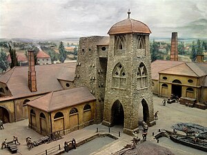
The first blast furnace in Germany, as depicted in a miniature in the Deutsches Museum
The oldest known blast furnaces in the West were built in Dürstel in Switzerland, the Märkische Sauerland in Germany, and at Lapphyttan in Sweden, where the complex was active between 1205 and 1300.[35] At Noraskog in the Swedish parish of Järnboås, traces of even earlier blast furnaces have been found, possibly from around 1100.[36] These early blast furnaces, like the Chinese examples, were very inefficient compared to those used today. The iron from the Lapphyttan complex was used to produce balls of wrought iron known as osmonds, and these were traded internationally – a possible reference occurs in a treaty with Novgorod from 1203 and several certain references in accounts of English customs from the 1250s and 1320s. Other furnaces of the 13th to 15th centuries have been identified in Westphalia.[37]
The technology required for blast furnaces may have either been transferred from China, or may have been an indigenous innovation. Al-Qazvini in the 13th century and other travellers subsequently noted an iron industry in the Alburz Mountains to the south of the Caspian Sea. This is close to the silk route, so that the use of technology derived from China is conceivable. Much later descriptions record blast furnaces about three metres high.[38] As the Varangian Rus’ people from Scandinavia traded with the Caspian (using their Volga trade route), it is possible that the technology reached Sweden by this means.[39] The step from bloomery to true blast furnace is not big. Simply just building a bigger furnace and using bigger bellows to increase the volume of the blast and hence the amount of oxygen leads inevitably into higher temperatures, bloom melting into liquid iron, and cast iron flowing from the smelters. The Vikings are known to have used double bellows, which greatly increases the volumetric flow of the blast.[40]
The Caspian region may also have been the source for the design of the furnace at Ferriere, described by Filarete,[41] involving a water-powered bellows at Semogo [it] in Valdidentro in northern Italy in 1226. In a two-stage process the molten iron was tapped twice a day into water, thereby granulating it.[42]
Cistercian contributions[edit]
The General Chapter of the Cistercian monks spread some technological advances across Europe. This may have included the blast furnace, as the Cistercians are known to have been skilled metallurgists.[43] According to Jean Gimpel, their high level of industrial technology facilitated the diffusion of new techniques: «Every monastery had a model factory, often as large as the church and only several feet away, and waterpower drove the machinery of the various industries located on its floor.» Iron ore deposits were often donated to the monks along with forges to extract the iron, and after a time surpluses were offered for sale. The Cistercians became the leading iron producers in Champagne, France, from the mid-13th century to the 17th century,[44] also using the phosphate-rich slag from their furnaces as an agricultural fertilizer.[45]
Archaeologists are still discovering the extent of Cistercian technology.[46] At Laskill, an outstation of Rievaulx Abbey and the only medieval blast furnace so far identified in Britain, the slag produced was low in iron content.[47] Slag from other furnaces of the time contained a substantial concentration of iron, whereas Laskill is believed to have produced cast iron quite efficiently.[47][48][49] Its date is not yet clear, but it probably did not survive until Henry VIII’s Dissolution of the Monasteries in the late 1530s, as an agreement (immediately after that) concerning the «smythes» with the Earl of Rutland in 1541 refers to blooms.[50] Nevertheless, the means by which the blast furnace spread in medieval Europe has not finally been determined.
Origin and spread of early modern blast furnaces[edit]

Period drawing of an 18th-century blast furnace

Early modern blast furnace pictured in the former coat of arms of Lohtaja
Due to the increased demand for iron for casting cannons, the blast furnace came into widespread use in France in the mid 15th century.[51][52]
The direct ancestor of those used in France and England was in the Namur region, in what is now Wallonia (Belgium). From there, they spread first to the Pays de Bray on the eastern boundary of Normandy and from there to the Weald of Sussex, where the first furnace (called Queenstock) in Buxted was built in about 1491, followed by one at Newbridge in Ashdown Forest in 1496. They remained few in number until about 1530 but many were built in the following decades in the Weald, where the iron industry perhaps reached its peak about 1590. Most of the pig iron from these furnaces was taken to finery forges for the production of bar iron.[53]
The first British furnaces outside the Weald appeared during the 1550s, and many were built in the remainder of that century and the following ones. The output of the industry probably peaked about 1620, and was followed by a slow decline until the early 18th century. This was apparently because it was more economic to import iron from Sweden and elsewhere than to make it in some more remote British locations. Charcoal that was economically available to the industry was probably being consumed as fast as the wood to make it grew.[54]
The first blast furnace in Russia opened in 1637 near Tula and was called the Gorodishche Works. The blast furnace spread from there to central Russia and then finally to the Urals.[55]
Coke blast furnaces[edit]


Charging the experimental blast furnace, Fixed Nitrogen Research Laboratory, Washington D.C., 1930
In 1709, at Coalbrookdale in Shropshire, England, Abraham Darby began to fuel a blast furnace with coke instead of charcoal. Coke’s initial advantage was its lower cost, mainly because making coke required much less labor than cutting trees and making charcoal, but using coke also overcame localized shortages of wood, especially in Britain and on the Continent. Metallurgical grade coke will bear heavier weight than charcoal, allowing larger furnaces.[56][57] A disadvantage is that coke contains more impurities than charcoal, with sulfur being especially detrimental to the iron’s quality. Coke’s impurities were more of a problem before hot blast reduced the amount of coke required and before furnace temperatures were hot enough to make slag from limestone free flowing. (Limestone ties up sulfur. Manganese may also be added to tie up sulfur.)[58]: 123–125 [59][60][51]: 122–123

Remnants of a blast furnace in Russia built in the early 18th century. It was first commissioned in 1715 by order of Peter the Great with the help of Holland masters.[citation needed]
Coke iron was initially only used for foundry work, making pots and other cast iron goods. Foundry work was a minor branch of the industry, but Darby’s son built a new furnace at nearby Horsehay, and began to supply the owners of finery forges with coke pig iron for the production of bar iron. Coke pig iron was by this time cheaper to produce than charcoal pig iron. The use of a coal-derived fuel in the iron industry was a key factor in the British Industrial Revolution.[61][62][63] Darby’s original blast furnace has been archaeologically excavated and can be seen in situ at Coalbrookdale, part of the Ironbridge Gorge Museums. Cast iron from the furnace was used to make girders for the world’s first iron bridge in 1779. The Iron Bridge crosses the River Severn at Coalbrookdale and remains in use for pedestrians.
Steam-powered blast[edit]
The steam engine was applied to power blast air, overcoming a shortage of water power in areas where coal and iron ore were located. This was first done at Coalbrookdale where a steam engine replaced a horse-powered pump in 1742.[64] Such engines were used to pump water to a reservoir above the furnace. The first engines used to blow cylinders directly was supplied by Boulton and Watt to John Wilkinson’s New Willey Furnace.[65] This powered a cast iron blowing cylinder, which had been invented by his father Isaac Wilkinson. He patented such cylinders in 1736,[66] to replace the leather bellows, which wore out quickly. Isaac was granted a second patent, also for blowing cylinders, in 1757.[67] The steam engine and cast iron blowing cylinder led to a large increase in British iron production in the late 18th century.[51]
Hot blast[edit]
Hot blast was the single most important advance in fuel efficiency of the blast furnace and was one of the most important technologies developed during the Industrial Revolution.[68][69] Hot blast was patented by James Beaumont Neilson at Wilsontown Ironworks in Scotland in 1828. Within a few years of the introduction, hot blast was developed to the point where fuel consumption was cut by one-third using coke or two-thirds using coal, while furnace capacity was also significantly increased. Within a few decades, the practice was to have a «stove» as large as the furnace next to it into which the waste gas (containing CO) from the furnace was directed and burnt. The resultant heat was used to preheat the air blown into the furnace.[70]
Hot blast enabled the use of raw anthracite coal, which was difficult to light, to the blast furnace. Anthracite was first tried successfully by George Crane at Ynyscedwyn Ironworks in south Wales in 1837.[71] It was taken up in America by the Lehigh Crane Iron Company at Catasauqua, Pennsylvania, in 1839. Anthracite use declined when very high capacity blast furnaces requiring coke were built in the 1870s.
Modern applications of the blast furnace[edit]
Iron blast furnaces[edit]
The blast furnace remains an important part of modern iron production. Modern furnaces are highly efficient, including Cowper stoves to pre-heat the blast air and employ recovery systems to extract the heat from the hot gases exiting the furnace. Competition in industry drives higher production rates. The largest blast furnace in the world is in South Korea, with a volume around 6,000 m3 (210,000 cu ft). It can produce around 5,650,000 tonnes (5,560,000 LT) of iron per year.[72]
This is a great increase from the typical 18th-century furnaces, which averaged about 360 tonnes (350 long tons; 400 short tons) per year. Variations of the blast furnace, such as the Swedish electric blast furnace, have been developed in countries which have no native coal resources.
According to Global Energy Monitor the blast furnace is likely to become obsolete to meet climate change objectives of reducing carbon dioxide emission,[73] but BHP disagrees.[74] An alternative process involving direct reduced iron is likely to succeed it,[citation needed] but this also needs to use a blast furnace to melt the iron and remove the gangue (impurities) unless the ore is very high quality.[74]
Oxygen blast furnace[edit]
|
This section needs expansion. You can help by adding to it. (July 2021) |
The oxygen blast furnace (OBF) process has been extensively studied theoretically because of the potentials of promising energy conservation and CO2 emission reduction.[75] This type may be the most suitable for use with CCS.[74]the main blast furnace has of three levels of reduction zones reduction zone (523–973k),slag formation zone (1073–1273k), combustion zone (1773–1873k)
Lead blast furnaces[edit]
Blast furnaces are currently rarely used in copper smelting, but modern lead smelting blast furnaces are much shorter than iron blast furnaces and are rectangular in shape.[76] The overall shaft height is around 5 to 6 m.[77] Modern lead blast furnaces are constructed using water-cooled steel or copper jackets for the walls, and have no refractory linings in the side walls.[76] The base of the furnace is a hearth of refractory material (bricks or castable refractory).[76] Lead blast furnaces are often open-topped rather than having the charging bell used in iron blast furnaces.[78]
The blast furnace used at the Nyrstar Port Pirie lead smelter differs from most other lead blast furnaces in that it has a double row of tuyeres rather than the single row normally used.[77] The lower shaft of the furnace has a chair shape with the lower part of the shaft being narrower than the upper.[77] The lower row of tuyeres being located in the narrow part of the shaft.[77] This allows the upper part of the shaft to be wider than the standard.[77]
Zinc blast furnaces (Imperial Smelting Furnaces)[edit]
The blast furnaces used in the Imperial Smelting Process («ISP») were developed from the standard lead blast furnace, but are fully sealed.[79] This is because the zinc produced by these furnaces is recovered as metal from the vapor phase, and the presence of oxygen in the off-gas would result in the formation of zinc oxide.[79]
Blast furnaces used in the ISP have a more intense operation than standard lead blast furnaces, with higher air blast rates per m2 of hearth area and a higher coke consumption.[79]
Zinc production with the ISP is more expensive than with electrolytic zinc plants, so several smelters operating this technology have closed in recent years.[80] However, ISP furnaces have the advantage of being able to treat zinc concentrates containing higher levels of lead than can electrolytic zinc plants.[79]
Manufacture of stone wool[edit]
Stone wool or rock wool is a spun mineral fibre used as an insulation product and in hydroponics. It is manufactured in a blast furnace fed with diabase rock which contains very low levels of metal oxides. The resultant slag is drawn off and spun to form the rock wool product.[81] Very small amounts of metals are also produced which are an unwanted by-product.
Modern iron process[edit]

Blast furnace placed in an installation
- Iron ore + limestone sinter
- Coke
- Elevator
- Feedstock inlet
- Layer of coke
- Layer of sinter pellets of ore and limestone
- Hot blast (around 1200 °C)
- Removal of slag
- Tapping of molten pig iron
- Slag pot
- Torpedo car for pig iron
- Dust cyclone for separation of solid particles
- Cowper stoves for hot blast
- Smoke stack
- Feed air for Cowper stoves (air pre-heaters)
- Powdered coal
- Coke oven
- Coke
- Blast furnace gas downcomer
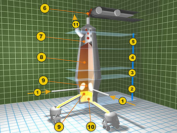
Blast furnace diagram
- Hot blast from Cowper stoves
- Melting zone (bosh)
- Reduction zone of ferrous oxide (barrel)
- Reduction zone of ferric oxide (stack)
- Pre-heating zone (throat)
- Feed of ore, limestone, and coke
- Exhaust gases
- Column of ore, coke and limestone
- Removal of slag
- Tapping of molten pig iron
- Collection of waste gases
|
|
This section needs to be updated. The reason given is: hydrogen and ccs are mentioned in another section but info is out of date — I guess the process should be described in this section. Please help update this article to reflect recent events or newly available information. (July 2021) |
Modern furnaces are equipped with an array of supporting facilities to increase efficiency, such as ore storage yards where barges are unloaded. The raw materials are transferred to the stockhouse complex by ore bridges, or rail hoppers and ore transfer cars. Rail-mounted scale cars or computer controlled weight hoppers weigh out the various raw materials to yield the desired hot metal and slag chemistry. The raw materials are brought to the top of the blast furnace via a skip car powered by winches or conveyor belts.[82]
There are different ways in which the raw materials are charged into the blast furnace. Some blast furnaces use a «double bell» system where two «bells» are used to control the entry of raw material into the blast furnace. The purpose of the two bells is to minimize the loss of hot gases in the blast furnace. First, the raw materials are emptied into the upper or small bell which then opens to empty the charge into the large bell. The small bell then closes, to seal the blast furnace, while the large bell rotates to provide specific distribution of materials before dispensing the charge into the blast furnace.[83][84] A more recent design is to use a «bell-less» system. These systems use multiple hoppers to contain each raw material, which is then discharged into the blast furnace through valves.[83] These valves are more accurate at controlling how much of each constituent is added, as compared to the skip or conveyor system, thereby increasing the efficiency of the furnace. Some of these bell-less systems also implement a discharge chute in the throat of the furnace (as with the Paul Wurth top) in order to precisely control where the charge is placed.[85]
The iron making blast furnace itself is built in the form of a tall structure, lined with refractory brick, and profiled to allow for expansion of the charged materials as they heat during their descent, and subsequent reduction in size as melting starts to occur. Coke, limestone flux, and iron ore (iron oxide) are charged into the top of the furnace in a precise filling order which helps control gas flow and the chemical reactions inside the furnace. Four «uptakes» allow the hot, dirty gas high in carbon monoxide content to exit the furnace throat, while «bleeder valves» protect the top of the furnace from sudden gas pressure surges. The coarse particles in the exhaust gas settle in the «dust catcher» and are dumped into a railroad car or truck for disposal, while the gas itself flows through a venturi scrubber and/or electrostatic precipitators and a gas cooler to reduce the temperature of the cleaned gas.[82]
The «casthouse» at the bottom half of the furnace contains the bustle[clarification needed] pipe, water cooled copper tuyeres and the equipment for casting the liquid iron and slag. Once a «taphole» is drilled through the refractory clay plug, liquid iron and slag flow down a trough through a «skimmer» opening, separating the iron and slag. Modern, larger blast furnaces may have as many as four tapholes and two casthouses.[82] Once the pig iron and slag has been tapped, the taphole is again plugged with refractory clay.
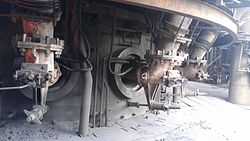
Tuyeres of Blast Furnace at Gerdau, Brazil
The tuyeres are used to implement a hot blast, which is used to increase the efficiency of the blast furnace. The hot blast is directed into the furnace through water-cooled copper nozzles called tuyeres near the base. The hot blast temperature can be from 900 °C to 1300 °C (1600 °F to 2300 °F) depending on the stove design and condition. The temperatures they deal with may be 2000 °C to 2300 °C (3600 °F to 4200 °F). Oil, tar, natural gas, powdered coal and oxygen can also be injected into the furnace at tuyere level to combine with the coke to release additional energy and increase the percentage of reducing gases present which is necessary to increase productivity.[82]
The exhaust gasses of a blast furnace are generally cleaned in the dust collector – such as an inertial separator, a baghouse, or an electrostatic precipitator. Each type of dust collector has strengths and weaknesses – some collect fine particles, some coarse particles, some collect electrically charged particles. Effective exhaust clearing relies on multiple stages of treatment.[86] Waste heat is usually collected from the exhaust gases, for example by the use of a Cowper stove, a variety of heat exchanger.
The IEA Green House Gas R&D Programme (IEAGHG) has shown that in an integrated steel plant, 70% of the CO2 is directly from the blast furnace gas (BFG). It is possible to use carbon capture technology on the BFG before the BFG goes on to be used for heat exchange processes within the plant. In 2000, the IEAGHG estimated using that chemical absorption to capture BFG would cost $35/t of CO2 (an additional $8–20/t of CO2 would be required for CO2 transportation and storage). This would make the entire steel production process in a plant 15–20% more expensive.[87]

Environmental impact[edit]
|
This section needs expansion. You can help by adding to it. (July 2021) |
The results showed that global warming potential and acidification potential were the most significant environmental impacts. On average producing a tonne of steel emits 1.8 tonnes of CO2.[6] However, a steel mill using a top gas recycling blast furnace (TGRBF) producing a tonne of steel will emit 0.8 to 1.3 tonnes of CO2 depending upon the recycle rate of the TGRBF.[88]
Decommissioned blast furnaces as museum sites[edit]
For a long time, it was normal procedure for a decommissioned blast furnace to be demolished and either be replaced with a newer, improved one, or to have the entire site demolished to make room for follow-up use of the area. In recent decades, several countries have realized the value of blast furnaces as a part of their industrial history. Rather than being demolished, abandoned steel mills were turned into museums or integrated into multi-purpose parks. The largest number of preserved historic blast furnaces exists in Germany; other such sites exist in Spain, France, the Czech Republic, Great Britain. Japan, Luxembourg, Poland, Romania, Mexico, Russia and the United States.
Gallery[edit]
-

Abandoned blast furnace in Sestao, Spain. The furnace itself is inside the central girderwork.
-

Part of the gas cleaning system of a blast furnace in Monclova, Mexico. This one is about to be de-commissioned and replaced.


See also[edit]
- Basic oxygen furnace
- Blast furnace zinc smelting process
- Crucible steel
- Extraction of iron
- Water gas, produced by a «steam blast»
- FINEX
- Flodin process
- Ironworks and steelworks in England, which covers ironworks of all kinds.
- Shaft furnace breather
References[edit]
- ^ See: Draft (boiler)
- ^ Schmult, Brian (2016). «Evolution of the Hopewell Furnace Blast Machinery». IA. The Journal of the Society for Industrial Archeology. 42 (2): 5–22.
- ^ Development of heat transfer circuits in the blast furnace, IOP Conference Series: Materials Science and Engineering
- ^ P J Wand, «Copper smelting at Electrolytic Refining and Smelting Company of Australia Ltd., Port Kembla, N.S.W.», in: Mining and Metallurgical Practices in Australasia: The Sir Maurice Mawby Memorial Volume, Ed J T Woodcock (The Australasian Institute of Mining and Metallurgy: Melbourne, 1980) 335–340.
- ^ R J Sinclair, The Extractive Metallurgy of Lead (The Australasian Institute of Mining and Metallurgy: Melbourne, 2009), 9–12.
- ^ a b Pooler, Michael (January 2019). «Cleaning up steel is key to tackling climate change». Financial Times. Archived from the original on 10 December 2022. Retrieved 7 July 2021.
- ^ Oeters, Franz; Ottow, Manfred; Meiler, Heinrich; Lüngen, Hans Bodo; Koltermann, Manfred; Buhr, Andreas; Yagi, Jun-Ichiro; Formanek, Lothar; Rose (2006). «Iron». Ullmann’s Encyclopedia of Industrial Chemistry. Weinheim: Wiley-VCH. doi:10.1002/14356007.a14_461.pub2.
- ^ a b «Blast Furnace». Science Aid. Archived from the original on 17 December 2007. Retrieved 30 December 2007.
- ^ a b c d e f Rayner-Canham & Overton (2006), Descriptive Inorganic Chemistry, Fourth Edition, New York: W. H. Freeman and Company, pp. 534–535, ISBN 978-0-7167-7695-6
- ^ Dr. K. E. Lee, Form Two Science (Biology Chemistry Physics)
- ^ Flowers, Paul; Robinson, William R.; Langley, Richard; Theopold, Klaus (2015). «Occurrence, Preparation, and Properties of Transition Metals and Their Compounds». Chemistry. OpenStax. ISBN 978-1938168390.
- ^ tec-science (21 June 2018). «From pig iron to crude steel». tec-science. Retrieved 2 November 2019.
- ^ Wang, Peng; Ryberg, Morten; Yang, Yi; Feng, Kuishuang; Kara, Sami; Hauschild, Michael; Chen, Wei-Qiang (6 April 2021). «Efficiency stagnation in global steel production urges joint supply- and demand-side mitigation efforts». Nature Communications. 12 (1): 2066. Bibcode:2021NatCo..12.2066W. doi:10.1038/s41467-021-22245-6. ISSN 2041-1723. PMC 8024266. PMID 33824307.
- ^ De Ras, Kevin; Van De Vijver, Ruben; Galvita, Vladimir V.; Marin, Guy B.; Van Geem, Kevin M. (1 December 2019). «Carbon capture and utilization in the steel industry: challenges and opportunities for chemical engineering». Current Opinion in Chemical Engineering. 26: 81–87. doi:10.1016/j.coche.2019.09.001. ISSN 2211-3398. S2CID 210619173.
- ^ http://www.ulcos.org Archived 21 November 2008 at the Wayback Machine
- ^ ICIT-Revue de Métallurgie, September and October issues, 2009
- ^ Peter J. Golas (1999). Science and Civilisation in China: Volume 5, Chemistry and Chemical Technology, Part 13, Mining. Cambridge University Press. p. 152. ISBN 978-0-521-58000-7.
…earliest blast furnace discovered in China from about the first century AD
- ^ Simcoe, Charles R. «The Age of Steel: Part II.» Advanced Materials & Processes 172.4 (2014): 32–33. Academic Search Premier.
- ^ «The Earliest Use of Iron in China» by Donald B. Wagner in Metals in Antiquity, by Suzanne M. M. Young, A. Mark Pollard, Paul Budd and Robert A. Ixer (BAR International Series, 792), Oxford: Archaeopress, 1999, pp. 1–9.
- ^ Wagner 2008, p. 230.
- ^ Ebrey, p. 30.
- ^ Early iron in China, Korea, and Japan Archived 5 February 2007 at the Wayback Machine, Donald B. Wagner, March 1993
- ^ Wagner 2008, p. 6.
- ^ Needham, Joseph (1986), Science and Civilisation in China, Volume 4: Physics and Physical Technology, Part 2, Mechanical Engineering, Taipei: Cambridge University Press, p. 370, ISBN 0-521-05803-1
- ^ Hong-Sen Yan, Marco Ceccarelli (2009). International Symposium on History of Machines and Mechanisms. Springer Science and Business Media. pp. 235–249. ISBN 978-1-4020-9484-2.
- ^ Needham 1986, pp. 118–119.
- ^ The Coming of the Ages of Steel. Brill Archive. 1961. p. 54. GGKEY:DN6SZTCNQ3G.
- ^ Donald B. Wagner, ‘Chinese blast furnaces from the 10th to the 14th century’ Historical Metallurgy 37(1) (2003), 25–37; originally published in West Asian Science, Technology, and Medicine 18 (2001), 41–74.
- ^ Ebrey, p. 158.
- ^ Wagner 2008, p. 169.
- ^ Wagner 2008, p. 1.
- ^ Liang 2006.
- ^ Julius H. Strassburger (1969). Blast Furnace-theory and Practice. Gordon and Breach Science Publishers. p. 4. ISBN 978-0-677-10420-1. Retrieved 12 July 2012.
- ^ Douglas Alan Fisher, Excerpt from The Epic of Steel Archived 25 February 2007 at the Wayback Machine, Davis Town Museum & Harper & Row, NY 1963.
- ^ Jockenhövel, Albrecht et al. (1997) «Archaeological Investigations on the Beginning of Blast Furnace-Technology in Central Europe» Archived 24 February 2013 at the Wayback Machine Abteilung für Ur- und Frühgeschichtliche Archäologie, Westfälische Wilhelms-Universität Münster; abstract published as: Jockenhövel, A. (1997) «Archaeological Investigations on the Beginning of Blast Furnace-Technology in Central Europe» pp. 56–58 In Crew, Peter and Crew, Susan (editors) (1997) Early Ironworking in Europe: Archaeology and Experiment: Abstracts of the International Conference at Plas Tan y Bwlch 19–25 September 1997 (Plas Tan y Bwlch Occasional Papers No 3) Snowdonia National Park Study Centre, Gwynedd, Wales, OCLC 470699473; archived here [1] by WebCite on 11 March 2012
- ^ A. Wetterholm, ‘Blast furnace studies in Nora bergslag’ (Örebro universitet 1999, Järn och Samhälle) ISBN 91-7668-204-8
- ^ N. Bjökenstam, ‘The Blast Furnace in Europe during the Middle Ages: part of a new system for producing wrought iron’ in G. Magnusson, The Importance of Ironmaking: Technological Innovation and Social Change I (Jernkontoret, Stockholm 1995), 143–153 and other papers in the same volume.
- ^ Wagner 2008, 349–351.
- ^ Wagner 2008, 354.
- ^ Markewitz, Darrell (25 March 2006). «Adventures in Early Iron Production – An overview of experimental iron smelts, 2001–2005». www.warehamforge.ca. Archived from the original on 22 September 2015.
- ^ Wagner 2008, 355.
- ^ B. G. Awty, ‘The blast funace in the Renaissance period: haut fournau or fonderie ‘, Transactions of Newcomen Society 61 (1989–90). 67.
- ^ Woods, p. 34.
- ^ Gimpel, p. 67.
- ^ Woods, p. 35.
- ^ Woods, p. 36.
- ^ a b Woods, p. 37.
- ^ R. W. Vernon, G. McDonnell and A. Schmidt (1998). «An integrated geophysical and analytical appraisal of early iron-working: three case studies». Historical Metallurgy. 32 (2): 72–75, 79.
- ^ David Derbyshire, ‘Henry «Stamped Out Industrial Revolution»‘ Archived 13 June 2014 at the Wayback Machine, The Daily Telegraph (21 June 2002); cited by Woods.
- ^ Schubert, H. R. (1957), History of the British iron and steel industry from c. 450 BC to AD 1775, Routledge & Kegan Paul, pp. 395–397
- ^ a b c Tylecote, R. F. (1992). A History of Metallurgy, Second Edition. London: Maney Publishing, for the Institute of Materials. ISBN 978-0901462886.
- ^ Merson, John (1990). The Genius That Was China: East and West in the Making of the Modern World. Woodstock, New York: The Overlook Press. p. 69. ISBN 0-87951-397-7A companion to the PBS Series «The Genius That Was China»
{{cite book}}: CS1 maint: postscript (link) - ^ Awty, Brian; Whittick, Christopher (2002). «The Lordship of Canterbury, iron-founding at Buxted, and the continental antecedents of cannon-founding in the Weald». Sussex Archaeological Collections. 140: 71–81. doi:10.5284/1085896.
- ^ P. W. King, ‘The production and consumption of iron in early modern England and Wales’ Economic History Review LVIII(1), 1–33; G. Hammersley, ‘The charcoal iron industry and its fuel 1540–1750’ Economic History Review Ser. II, XXVI (1973), pp. 593–613.
- ^ Yakovlev, V. B. (1957), «Development of Wrought Iron Production», Metallurgist, New York: Springer, 1 (8): 545, doi:10.1007/BF00732452, S2CID 137551466
- ^
Landes, David. S. (1969). The Unbound Prometheus: Technological Change and Industrial Development in Western Europe from 1750 to the Present. Cambridge; New York: Press Syndicate of the University of Cambridge. pp. 90–93. ISBN 0-521-09418-6. - ^
Rosen, William (2012). The Most Powerful Idea in the World: A Story of Steam, Industry and Invention. University of Chicago Press. p. 149. ISBN 978-0226726342. - ^ Tylecote, R. F. (1992). A History of Metallurgy, Second Edition. London: Maney Publishing, for the Institute of Materials. ISBN 978-0901462886.
- ^ McNeil, Ian (1990). An Encyclopedia of the History of Technology. London: Routledge. ISBN 0415147921.
- ^ «Coke for Blast Furnace Ironmaking». steel.org. Archived from the original on 8 February 2017.
- ^ Raistrick, Arthur (1953), Dynasty of Iron Founders: The Darbys and Coalbrookedale, York: Longmans, Green
- ^ Hyde
- ^ Trinder, Barrie Stuart; Trinder, Barrie (2000), The Industrial Revolution in Shropshire, Chichester: Phillimore, ISBN 1-86077-133-5
- ^ A. Raistrick, Dynasty of ironmasters (Sessions, York, 1989), 138–139.
- ^ H.W. Dickinson and Rhys Jenkins, James Watt and the steam engine (Moorland, Ashbourne 1981 edn), 111–112.
- ^ English patent, no.553.
- ^ English patent, no.713.
- ^
Landes, David. S. (1969). The Unbound Prometheus: Technological Change and Industrial Development in Western Europe from 1750 to the Present. Cambridge; New York: Press Syndicate of the University of Cambridge. p. 92. ISBN 0-521-09418-6. - ^ Ayres, Robert (1989). «Technological Transformations and Long Waves» (PDF): 21. Archived from the original (PDF) on 1 March 2012. Retrieved 17 October 2013<Fig. 7 shows C/Fe ratio time series> CS1 maint: postscript (link)
- ^ Birch, pp. 181–189.
- ^ Hyde, p. 159.
- ^ «POSCO Gwangyang blast furnace emerges as world largest», The Dong-a Ilbo, 10 June 2013
- ^ «Steel sector may be saddled with up to $70 bln stranded assets -report». Reuters. 29 June 2021. Retrieved 10 July 2021.
- ^ a b c «Pathways to decarbonisation episode two: steelmaking technology». Archived from the original on 5 November 2020.
- ^ Zhang, Wei; Dai, Jing; Li, Chengzhi; Yu, Xiaobing; Xue, Zhengliang; Saxén, Henrik (January 2021). «A Review on Explorations of the Oxygen Blast Furnace Process». Steel Research International. 92 (1): 2000326. doi:10.1002/srin.202000326. ISSN 1611-3683. S2CID 224952826.
- ^ a b c R J Sinclair, The Extractive Metallurgy of Lead (The Australasian Institute of Mining and Metallurgy: Melbourne, 2009), 75.
- ^ a b c d e R J Sinclair, The Extractive Metallurgy of Lead (The Australasian Institute of Mining and Metallurgy: Melbourne, 2009), 77.
- ^ R J Sinclair, The Extractive Metallurgy of Lead (The Australasian Institute of Mining and Metallurgy: Melbourne, 2009), 76.
- ^ a b c d R J Sinclair, The Extractive Metallurgy of Lead (The Australasian Institute of Mining and Metallurgy: Melbourne, 2009), 89.
- ^ R J Sinclair, The Extractive Metallurgy of Lead (The Australasian Institute of Mining and Metallurgy: Melbourne, 2009), 90.
- ^ «What is stone wool?». rockwool.co.uk. Archived from the original on 10 February 2010.
- ^ a b c d American Iron and Steel Institute (2005). How a Blast Furnace Works. steel.org.
- ^ a b McNeil, Ian (1990), An encyclopaedia of the history of technology, Taylor & Francis, p. 163, ISBN 0-415-01306-2
- ^ Strassburger, Julius H. (1969), Blast furnace: Theory and Practice, Taylor & Francis, p. 564, ISBN 0-677-10420-0
- ^ Whitfield, Peter, Design and Operation of a Gimbal Top Charging System (PDF), archived from the original (PDF) on 5 March 2009, retrieved 22 June 2008
- ^ «Comparison of techniques employed at Scunthorpe Integrated Steelworks with those in the BAT Conclusions for Iron and Steel Production published in the Official Journal of the European Union» (PDF). HM Government UK. 8 March 2012. Retrieved 19 January 2021.
- ^ IEA-GHG, 2000. Greenhouse Gas Emissions from Major Industrial Sources – Iron and Steel Production. Report no. PH3/30. Cheltenham, UK, IEA Greenhouse Gas R&D Programme. https://ieaghg.org/docs/General_Docs/Reports/PH3-30%20iron-steel.pdf Accessed July 30, 2021.
- ^ Ho, Minh T.; Bustamante, Andrea; Wiley, Dianne E. (November 2013). «Comparison of CO2 capture economics for iron and steel mills». International Journal of Greenhouse Gas Control. 19: 145–159. doi:10.1016/j.ijggc.2013.08.003.
Bibliography[edit]
- Birch, Alan (2005), The Economic History of the British Iron and Steel Industry, 1784–1879, Routledge, ISBN 0-415-38248-3
- Ebrey, Patricia Buckley; Walthall, Anne; Palais, James B. (2005), East Asia: A Cultural, Social, and Political History, Boston: Houghton Mifflin, ISBN 0-618-13384-4
- Gimpel, Jean (1976), The Medieval Machine: The Industrial Revolution of the Middle Ages, New York: Holt, Rinehart and Winston, ISBN 0-03-014636-4
- Hyde, Charles K. (1977), Technological Change and the British iron industry, 1700–1870, Princeton: Princeton University Press, ISBN 0-691-05246-8
- Liang, Jieming (2006), Chinese Siege Warfare: Mechanical Artillery & Siege Weapons of Antiquity, Singapore, Republic of Singapore: Leong Kit Meng, ISBN 981-05-5380-3
- Wagner, Donald B. (2008), Science and Civilization in China Volume 5–11: Ferrous Metallurgy, Cambridge University Press[ISBN missing]
- Woods, Thomas (2005), How the Catholic Church Built Western Civilization, Washington, D.C.: Regnery Publ., ISBN 0-89526-038-7
External links[edit]
- American Iron and Steel Institute
- Blast Furnace animation
- Extensive picture gallery about all methods of making and shaping of iron and steel in North America and Europe. In German and English.
- Schematic diagram of blast furnace and Cowper stove
Former blast furnace in Port of Sagunt, Valencia, Spain.
A blast furnace is a type of metallurgical furnace used for smelting to produce industrial metals, generally pig iron, but also others such as lead or copper. Blast refers to the combustion air being «forced» or supplied above atmospheric pressure.[1]
In a blast furnace, fuel (coke), ores, and flux (limestone) are continuously supplied through the top of the furnace, while a hot blast of air (sometimes with oxygen enrichment) is blown into the lower section of the furnace through a series of pipes called tuyeres, so that the chemical reactions take place throughout the furnace as the material falls downward. The end products are usually molten metal and slag phases tapped from the bottom, and waste gases (flue gas) exiting from the top of the furnace.[2] The downward flow of the ore along with the flux in contact with an upflow of hot, carbon monoxide-rich combustion gases is a countercurrent exchange and chemical reaction process.[3]
In contrast, air furnaces (such as reverberatory furnaces) are naturally aspirated, usually by the convection of hot gases in a chimney flue. According to this broad definition, bloomeries for iron, blowing houses for tin, and smelt mills for lead would be classified as blast furnaces. However, the term has usually been limited to those used for smelting iron ore to produce pig iron, an intermediate material used in the production of commercial iron and steel, and the shaft furnaces used in combination with sinter plants in base metals smelting.[4][5]
Blast furnaces are estimated to have been responsible for over 4% of global greenhouse gas emissions between 1900 and 2015, but are difficult to decarbonize.[6]
Process engineering and chemistry[edit]
Charcoal burning iron blast furnace in Ohio, 1923
Blast furnaces operate on the principle of chemical reduction whereby carbon monoxide converts iron oxides to elemental iron. Blast furnaces differ from bloomeries and reverberatory furnaces in that in a blast furnace, flue gas is in direct contact with the ore and iron, allowing carbon monoxide to diffuse into the ore and reduce the iron oxide. The blast furnace operates as a countercurrent exchange process whereas a bloomery does not. Another difference is that bloomeries operate as a batch process whereas blast furnaces operate continuously for long periods. Continuous operation is also preferred because blast furnaces are difficult to start and stop. Also, the carbon in pig iron lowers the melting point below that of steel or pure iron; in contrast, iron does not melt in a bloomery.
Silica has to be removed from the pig iron. It reacts with calcium oxide (burned limestone) and forms silicates, which float to the surface of the molten pig iron as «slag». Historically, to prevent contamination from sulfur, the best quality iron was produced with charcoal.
The downward moving column of ore, flux, coke or charcoal and reaction products must be sufficiently porous for the flue gas to pass through. To ensure this permeability the particle size of the coke or charcoal is of great relevance. Therefore, the coke must be strong enough so it will not be crushed by the weight of the material above it. Besides the physical strength of its particles, the coke must also be low in sulfur, phosphorus, and ash.[7]
Rising carbon monoxide reduces iron oxides to pure iron through a series of reactions that occur at different areas within a blast furnace.
The main chemical reaction producing the molten iron is:
- Fe2O3 + 3CO → 2Fe + 3CO2[8]
This reaction might be divided into multiple steps, with the first being that preheated air blown into the furnace reacts with the carbon in the form of coke to produce carbon monoxide and heat:
- 2 C(s) + O2(g) → 2 CO(g)[9]
The hot carbon monoxide is the reducing agent for the iron ore and reacts with the iron oxide to produce molten iron and carbon dioxide. Depending on the temperature in the different parts of the furnace (warmest at the bottom) the iron is reduced in several steps. At the top, where the temperature usually is in the range between 200 °C and 700 °C, the iron oxide is partially reduced to iron(II,III) oxide, Fe3O4.
- 3 Fe2O3(s) + CO(g) → 2 Fe3O4(s) + CO2(g)[9]
The temperatures 850 °C, further down in the furnace, the iron(II,III) is reduced further to iron(II) oxide:
- Fe3O4(s) + CO(g) → 3 FeO(s) + CO2(g)[9]
Hot carbon dioxide, unreacted carbon monoxide, and nitrogen from the air pass up through the furnace as fresh feed material travels down into the reaction zone. As the material travels downward, the counter-current gases both preheat the feed charge and decompose the limestone to calcium oxide and carbon dioxide:
- CaCO3(s) → CaO(s) + CO2(g)[9]
The calcium oxide formed by decomposition reacts with various acidic impurities in the iron (notably silica), to form a fayalitic slag which is essentially calcium silicate, CaSiO
3:[8]
- SiO2 + CaO → CaSiO3[10][11]
As the iron(II) oxide moves down to the area with higher temperatures, ranging up to 1200 °C degrees, it is reduced further to iron metal:
- FeO(s) + CO(g) → Fe(s) + CO2(g)[9]
The carbon dioxide formed in this process is re-reduced to carbon monoxide by the coke:
- C(s) + CO2(g) → 2 CO(g)[9]
The temperature-dependent equilibrium controlling the gas atmosphere in the furnace is called the Boudouard reaction:
-
- 2CO ⇌ CO2 + C
The «pig iron» produced by the blast furnace has a relatively high carbon content of around 4–5% and usually contains too much sulphur, making it very brittle, and of limited immediate commercial use. Some pig iron is used to make cast iron. The majority of pig iron produced by blast furnaces undergoes further processing to reduce the carbon and sulphur content and produce various grades of steel used for construction materials, automobiles, ships and machinery. Desulphurisation usually takes place during the transport of the liquid steel to the steelworks. This is done by adding calcium oxide, which reacts with the iron sulfide contained in the pig iron to form calcium sulfide (called lime desulfurization).[12] In a further process step, the so-called basic oxygen steelmaking, the carbon is oxidized by blowing oxygen onto the liquid pig iron to form crude steel.
Although the efficiency of blast furnaces is constantly evolving, the chemical process inside the blast furnace remains the same. One of the biggest drawbacks of the blast furnaces is the inevitable carbon dioxide production as iron is reduced from iron oxides by carbon and as of 2016, there is no economical substitute – steelmaking is one of the largest industrial contributors of the CO2 emissions in the world (see greenhouse gases).[13] Several alternatives are being investigated such as plastic waste, biomass or hydrogen as reducing agent, which can substantially reduce the carbon emissions.[14]
The challenge set by the greenhouse gas emissions of the blast furnace is being addressed in an ongoing[when?] European Program called ULCOS (Ultra Low CO2 Steelmaking).[15] Several new process routes have been proposed and investigated in depth to cut specific emissions (CO2 per ton of steel) by at least 50%. Some rely on the capture and further storage (CCS) of CO2, while others choose decarbonizing iron and steel production, by turning to hydrogen, electricity and biomass.[16] In the nearer term, a technology that incorporates CCS into the blast furnace process itself and is called the Top-Gas Recycling Blast Furnace is under development, with a scale-up to a commercial size blast furnace under way.[needs update]
History[edit]
Cast iron has been found in China dating to the 5th century BC, but the earliest extant blast furnaces in China date to the 1st century AD and in the West from the High Middle Ages.[17] They spread from the region around Namur in Wallonia (Belgium) in the late 15th century, being introduced to England in 1491. The fuel used in these was invariably charcoal. The successful substitution of coke for charcoal is widely attributed to English inventor Abraham Darby in 1709. The efficiency of the process was further enhanced by the practice of preheating the combustion air (hot blast), patented by Scottish inventor James Beaumont Neilson in 1828.[18]
China[edit]
Archaeological evidence shows that bloomeries appeared in China around 800 BC. Originally it was thought that the Chinese started casting iron right from the beginning, but this theory has since been debunked[clarification needed] by the discovery of ‘more than ten’ iron digging implements found in the tomb of Duke Jing of Qin (d. 537 BC), whose tomb is located in Fengxiang County, Shaanxi (a museum exists on the site today).[19] There is however no evidence of the bloomery in China after the appearance of the blast furnace and cast iron. In China, blast furnaces produced cast iron, which was then either converted into finished implements in a cupola furnace, or turned into wrought iron in a fining hearth.[20]
Although cast iron farm tools and weapons were widespread in China by the 5th century BC, employing workforces of over 200 men in iron smelters from the 3rd century onward, the earliest blast furnaces constructed were attributed to the Han Dynasty in the 1st century AD.[21] These early furnaces had clay walls and used phosphorus-containing minerals as a flux.[22] Chinese blast furnaces ranged from around two to ten meters in height, depending on the region. The largest ones were found in modern Sichuan and Guangdong, while the ‘dwarf» blast furnaces were found in Dabieshan. In construction, they are both around the same level of technological sophistication [23]
The effectiveness of the Chinese human and horse powered blast furnaces was enhanced during this period by the engineer Du Shi (c. AD 31), who applied the power of waterwheels to piston-bellows in forging cast iron.[24] Early water-driven reciprocators for operating blast furnaces were built according to the structure of horse powered reciprocators that already existed. That is, the circular motion of the wheel, be it horse driven or water driven, was transferred by the combination of a belt drive, a crank-and-connecting-rod, other connecting rods, and various shafts, into the reciprocal motion necessary to operate a push bellow.[25][26] Donald Wagner suggests that early blast furnace and cast iron production evolved from furnaces used to melt bronze. Certainly, though, iron was essential to military success by the time the State of Qin had unified China (221 BC). Usage of the blast and cupola furnace remained widespread during the Song and Tang Dynasties.[27] By the 11th century, the Song Dynasty Chinese iron industry made a switch of resources from charcoal to coke in casting iron and steel, sparing thousands of acres of woodland from felling. This may have happened as early as the 4th century AD.[28][29]
The primary advantage of the early blast furnace was in large scale production and making iron implements more readily available to peasants.[30] Cast iron is more brittle than wrought iron or steel, which required additional fining and then cementation or co-fusion to produce, but for menial activities such as farming it sufficed. By using the blast furnace, it was possible to produce larger quantities of tools such as ploughshares more efficiently than the bloomery. In areas where quality was important, such as warfare, wrought iron and steel were preferred. Nearly all Han period weapons are made of wrought iron or steel, with the exception of axe-heads, of which many are made of cast iron.[31]
Blast furnaces were also later used to produce gunpowder weapons such as cast iron bomb shells and cast iron cannons during the Song dynasty.[32]
Medieval Europe[edit]
The simplest forge, known as the Corsican, was used prior to the advent of Christianity. Examples of improved bloomeries are the Stückofen [fr][33] (sometimes called wolf-furnace[34]), which remained until the beginning of the 19th century. Instead of using natural draught, air was pumped in by a trompe, resulting in better quality iron and an increased capacity. This pumping of air in with bellows is known as cold blast, and it increases the fuel efficiency of the bloomery and improves yield. They can also be built bigger than natural draught bloomeries.
Oldest European blast furnaces[edit]
The first blast furnace in Germany, as depicted in a miniature in the Deutsches Museum
The oldest known blast furnaces in the West were built in Dürstel in Switzerland, the Märkische Sauerland in Germany, and at Lapphyttan in Sweden, where the complex was active between 1205 and 1300.[35] At Noraskog in the Swedish parish of Järnboås, traces of even earlier blast furnaces have been found, possibly from around 1100.[36] These early blast furnaces, like the Chinese examples, were very inefficient compared to those used today. The iron from the Lapphyttan complex was used to produce balls of wrought iron known as osmonds, and these were traded internationally – a possible reference occurs in a treaty with Novgorod from 1203 and several certain references in accounts of English customs from the 1250s and 1320s. Other furnaces of the 13th to 15th centuries have been identified in Westphalia.[37]
The technology required for blast furnaces may have either been transferred from China, or may have been an indigenous innovation. Al-Qazvini in the 13th century and other travellers subsequently noted an iron industry in the Alburz Mountains to the south of the Caspian Sea. This is close to the silk route, so that the use of technology derived from China is conceivable. Much later descriptions record blast furnaces about three metres high.[38] As the Varangian Rus’ people from Scandinavia traded with the Caspian (using their Volga trade route), it is possible that the technology reached Sweden by this means.[39] The step from bloomery to true blast furnace is not big. Simply just building a bigger furnace and using bigger bellows to increase the volume of the blast and hence the amount of oxygen leads inevitably into higher temperatures, bloom melting into liquid iron, and cast iron flowing from the smelters. The Vikings are known to have used double bellows, which greatly increases the volumetric flow of the blast.[40]
The Caspian region may also have been the source for the design of the furnace at Ferriere, described by Filarete,[41] involving a water-powered bellows at Semogo [it] in Valdidentro in northern Italy in 1226. In a two-stage process the molten iron was tapped twice a day into water, thereby granulating it.[42]
Cistercian contributions[edit]
The General Chapter of the Cistercian monks spread some technological advances across Europe. This may have included the blast furnace, as the Cistercians are known to have been skilled metallurgists.[43] According to Jean Gimpel, their high level of industrial technology facilitated the diffusion of new techniques: «Every monastery had a model factory, often as large as the church and only several feet away, and waterpower drove the machinery of the various industries located on its floor.» Iron ore deposits were often donated to the monks along with forges to extract the iron, and after a time surpluses were offered for sale. The Cistercians became the leading iron producers in Champagne, France, from the mid-13th century to the 17th century,[44] also using the phosphate-rich slag from their furnaces as an agricultural fertilizer.[45]
Archaeologists are still discovering the extent of Cistercian technology.[46] At Laskill, an outstation of Rievaulx Abbey and the only medieval blast furnace so far identified in Britain, the slag produced was low in iron content.[47] Slag from other furnaces of the time contained a substantial concentration of iron, whereas Laskill is believed to have produced cast iron quite efficiently.[47][48][49] Its date is not yet clear, but it probably did not survive until Henry VIII’s Dissolution of the Monasteries in the late 1530s, as an agreement (immediately after that) concerning the «smythes» with the Earl of Rutland in 1541 refers to blooms.[50] Nevertheless, the means by which the blast furnace spread in medieval Europe has not finally been determined.
Origin and spread of early modern blast furnaces[edit]
Period drawing of an 18th-century blast furnace
Early modern blast furnace pictured in the former coat of arms of Lohtaja
Due to the increased demand for iron for casting cannons, the blast furnace came into widespread use in France in the mid 15th century.[51][52]
The direct ancestor of those used in France and England was in the Namur region, in what is now Wallonia (Belgium). From there, they spread first to the Pays de Bray on the eastern boundary of Normandy and from there to the Weald of Sussex, where the first furnace (called Queenstock) in Buxted was built in about 1491, followed by one at Newbridge in Ashdown Forest in 1496. They remained few in number until about 1530 but many were built in the following decades in the Weald, where the iron industry perhaps reached its peak about 1590. Most of the pig iron from these furnaces was taken to finery forges for the production of bar iron.[53]
The first British furnaces outside the Weald appeared during the 1550s, and many were built in the remainder of that century and the following ones. The output of the industry probably peaked about 1620, and was followed by a slow decline until the early 18th century. This was apparently because it was more economic to import iron from Sweden and elsewhere than to make it in some more remote British locations. Charcoal that was economically available to the industry was probably being consumed as fast as the wood to make it grew.[54]
The first blast furnace in Russia opened in 1637 near Tula and was called the Gorodishche Works. The blast furnace spread from there to central Russia and then finally to the Urals.[55]
Coke blast furnaces[edit]
Charging the experimental blast furnace, Fixed Nitrogen Research Laboratory, Washington D.C., 1930
In 1709, at Coalbrookdale in Shropshire, England, Abraham Darby began to fuel a blast furnace with coke instead of charcoal. Coke’s initial advantage was its lower cost, mainly because making coke required much less labor than cutting trees and making charcoal, but using coke also overcame localized shortages of wood, especially in Britain and on the Continent. Metallurgical grade coke will bear heavier weight than charcoal, allowing larger furnaces.[56][57] A disadvantage is that coke contains more impurities than charcoal, with sulfur being especially detrimental to the iron’s quality. Coke’s impurities were more of a problem before hot blast reduced the amount of coke required and before furnace temperatures were hot enough to make slag from limestone free flowing. (Limestone ties up sulfur. Manganese may also be added to tie up sulfur.)[58]: 123–125 [59][60][51]: 122–123
Remnants of a blast furnace in Russia built in the early 18th century. It was first commissioned in 1715 by order of Peter the Great with the help of Holland masters.[citation needed]
Coke iron was initially only used for foundry work, making pots and other cast iron goods. Foundry work was a minor branch of the industry, but Darby’s son built a new furnace at nearby Horsehay, and began to supply the owners of finery forges with coke pig iron for the production of bar iron. Coke pig iron was by this time cheaper to produce than charcoal pig iron. The use of a coal-derived fuel in the iron industry was a key factor in the British Industrial Revolution.[61][62][63] Darby’s original blast furnace has been archaeologically excavated and can be seen in situ at Coalbrookdale, part of the Ironbridge Gorge Museums. Cast iron from the furnace was used to make girders for the world’s first iron bridge in 1779. The Iron Bridge crosses the River Severn at Coalbrookdale and remains in use for pedestrians.
Steam-powered blast[edit]
The steam engine was applied to power blast air, overcoming a shortage of water power in areas where coal and iron ore were located. This was first done at Coalbrookdale where a steam engine replaced a horse-powered pump in 1742.[64] Such engines were used to pump water to a reservoir above the furnace. The first engines used to blow cylinders directly was supplied by Boulton and Watt to John Wilkinson’s New Willey Furnace.[65] This powered a cast iron blowing cylinder, which had been invented by his father Isaac Wilkinson. He patented such cylinders in 1736,[66] to replace the leather bellows, which wore out quickly. Isaac was granted a second patent, also for blowing cylinders, in 1757.[67] The steam engine and cast iron blowing cylinder led to a large increase in British iron production in the late 18th century.[51]
Hot blast[edit]
Hot blast was the single most important advance in fuel efficiency of the blast furnace and was one of the most important technologies developed during the Industrial Revolution.[68][69] Hot blast was patented by James Beaumont Neilson at Wilsontown Ironworks in Scotland in 1828. Within a few years of the introduction, hot blast was developed to the point where fuel consumption was cut by one-third using coke or two-thirds using coal, while furnace capacity was also significantly increased. Within a few decades, the practice was to have a «stove» as large as the furnace next to it into which the waste gas (containing CO) from the furnace was directed and burnt. The resultant heat was used to preheat the air blown into the furnace.[70]
Hot blast enabled the use of raw anthracite coal, which was difficult to light, to the blast furnace. Anthracite was first tried successfully by George Crane at Ynyscedwyn Ironworks in south Wales in 1837.[71] It was taken up in America by the Lehigh Crane Iron Company at Catasauqua, Pennsylvania, in 1839. Anthracite use declined when very high capacity blast furnaces requiring coke were built in the 1870s.
Modern applications of the blast furnace[edit]
Iron blast furnaces[edit]
The blast furnace remains an important part of modern iron production. Modern furnaces are highly efficient, including Cowper stoves to pre-heat the blast air and employ recovery systems to extract the heat from the hot gases exiting the furnace. Competition in industry drives higher production rates. The largest blast furnace in the world is in South Korea, with a volume around 6,000 m3 (210,000 cu ft). It can produce around 5,650,000 tonnes (5,560,000 LT) of iron per year.[72]
This is a great increase from the typical 18th-century furnaces, which averaged about 360 tonnes (350 long tons; 400 short tons) per year. Variations of the blast furnace, such as the Swedish electric blast furnace, have been developed in countries which have no native coal resources.
According to Global Energy Monitor the blast furnace is likely to become obsolete to meet climate change objectives of reducing carbon dioxide emission,[73] but BHP disagrees.[74] An alternative process involving direct reduced iron is likely to succeed it,[citation needed] but this also needs to use a blast furnace to melt the iron and remove the gangue (impurities) unless the ore is very high quality.[74]
Oxygen blast furnace[edit]
|
This section needs expansion. You can help by adding to it. (July 2021) |
The oxygen blast furnace (OBF) process has been extensively studied theoretically because of the potentials of promising energy conservation and CO2 emission reduction.[75] This type may be the most suitable for use with CCS.[74]the main blast furnace has of three levels of reduction zones reduction zone (523–973k),slag formation zone (1073–1273k), combustion zone (1773–1873k)
Lead blast furnaces[edit]
Blast furnaces are currently rarely used in copper smelting, but modern lead smelting blast furnaces are much shorter than iron blast furnaces and are rectangular in shape.[76] The overall shaft height is around 5 to 6 m.[77] Modern lead blast furnaces are constructed using water-cooled steel or copper jackets for the walls, and have no refractory linings in the side walls.[76] The base of the furnace is a hearth of refractory material (bricks or castable refractory).[76] Lead blast furnaces are often open-topped rather than having the charging bell used in iron blast furnaces.[78]
The blast furnace used at the Nyrstar Port Pirie lead smelter differs from most other lead blast furnaces in that it has a double row of tuyeres rather than the single row normally used.[77] The lower shaft of the furnace has a chair shape with the lower part of the shaft being narrower than the upper.[77] The lower row of tuyeres being located in the narrow part of the shaft.[77] This allows the upper part of the shaft to be wider than the standard.[77]
Zinc blast furnaces (Imperial Smelting Furnaces)[edit]
The blast furnaces used in the Imperial Smelting Process («ISP») were developed from the standard lead blast furnace, but are fully sealed.[79] This is because the zinc produced by these furnaces is recovered as metal from the vapor phase, and the presence of oxygen in the off-gas would result in the formation of zinc oxide.[79]
Blast furnaces used in the ISP have a more intense operation than standard lead blast furnaces, with higher air blast rates per m2 of hearth area and a higher coke consumption.[79]
Zinc production with the ISP is more expensive than with electrolytic zinc plants, so several smelters operating this technology have closed in recent years.[80] However, ISP furnaces have the advantage of being able to treat zinc concentrates containing higher levels of lead than can electrolytic zinc plants.[79]
Manufacture of stone wool[edit]
Stone wool or rock wool is a spun mineral fibre used as an insulation product and in hydroponics. It is manufactured in a blast furnace fed with diabase rock which contains very low levels of metal oxides. The resultant slag is drawn off and spun to form the rock wool product.[81] Very small amounts of metals are also produced which are an unwanted by-product.
Modern iron process[edit]
Blast furnace placed in an installation
- Iron ore + limestone sinter
- Coke
- Elevator
- Feedstock inlet
- Layer of coke
- Layer of sinter pellets of ore and limestone
- Hot blast (around 1200 °C)
- Removal of slag
- Tapping of molten pig iron
- Slag pot
- Torpedo car for pig iron
- Dust cyclone for separation of solid particles
- Cowper stoves for hot blast
- Smoke stack
- Feed air for Cowper stoves (air pre-heaters)
- Powdered coal
- Coke oven
- Coke
- Blast furnace gas downcomer
Blast furnace diagram
- Hot blast from Cowper stoves
- Melting zone (bosh)
- Reduction zone of ferrous oxide (barrel)
- Reduction zone of ferric oxide (stack)
- Pre-heating zone (throat)
- Feed of ore, limestone, and coke
- Exhaust gases
- Column of ore, coke and limestone
- Removal of slag
- Tapping of molten pig iron
- Collection of waste gases
|
|
This section needs to be updated. The reason given is: hydrogen and ccs are mentioned in another section but info is out of date — I guess the process should be described in this section. Please help update this article to reflect recent events or newly available information. (July 2021) |
Modern furnaces are equipped with an array of supporting facilities to increase efficiency, such as ore storage yards where barges are unloaded. The raw materials are transferred to the stockhouse complex by ore bridges, or rail hoppers and ore transfer cars. Rail-mounted scale cars or computer controlled weight hoppers weigh out the various raw materials to yield the desired hot metal and slag chemistry. The raw materials are brought to the top of the blast furnace via a skip car powered by winches or conveyor belts.[82]
There are different ways in which the raw materials are charged into the blast furnace. Some blast furnaces use a «double bell» system where two «bells» are used to control the entry of raw material into the blast furnace. The purpose of the two bells is to minimize the loss of hot gases in the blast furnace. First, the raw materials are emptied into the upper or small bell which then opens to empty the charge into the large bell. The small bell then closes, to seal the blast furnace, while the large bell rotates to provide specific distribution of materials before dispensing the charge into the blast furnace.[83][84] A more recent design is to use a «bell-less» system. These systems use multiple hoppers to contain each raw material, which is then discharged into the blast furnace through valves.[83] These valves are more accurate at controlling how much of each constituent is added, as compared to the skip or conveyor system, thereby increasing the efficiency of the furnace. Some of these bell-less systems also implement a discharge chute in the throat of the furnace (as with the Paul Wurth top) in order to precisely control where the charge is placed.[85]
The iron making blast furnace itself is built in the form of a tall structure, lined with refractory brick, and profiled to allow for expansion of the charged materials as they heat during their descent, and subsequent reduction in size as melting starts to occur. Coke, limestone flux, and iron ore (iron oxide) are charged into the top of the furnace in a precise filling order which helps control gas flow and the chemical reactions inside the furnace. Four «uptakes» allow the hot, dirty gas high in carbon monoxide content to exit the furnace throat, while «bleeder valves» protect the top of the furnace from sudden gas pressure surges. The coarse particles in the exhaust gas settle in the «dust catcher» and are dumped into a railroad car or truck for disposal, while the gas itself flows through a venturi scrubber and/or electrostatic precipitators and a gas cooler to reduce the temperature of the cleaned gas.[82]
The «casthouse» at the bottom half of the furnace contains the bustle[clarification needed] pipe, water cooled copper tuyeres and the equipment for casting the liquid iron and slag. Once a «taphole» is drilled through the refractory clay plug, liquid iron and slag flow down a trough through a «skimmer» opening, separating the iron and slag. Modern, larger blast furnaces may have as many as four tapholes and two casthouses.[82] Once the pig iron and slag has been tapped, the taphole is again plugged with refractory clay.
Tuyeres of Blast Furnace at Gerdau, Brazil
The tuyeres are used to implement a hot blast, which is used to increase the efficiency of the blast furnace. The hot blast is directed into the furnace through water-cooled copper nozzles called tuyeres near the base. The hot blast temperature can be from 900 °C to 1300 °C (1600 °F to 2300 °F) depending on the stove design and condition. The temperatures they deal with may be 2000 °C to 2300 °C (3600 °F to 4200 °F). Oil, tar, natural gas, powdered coal and oxygen can also be injected into the furnace at tuyere level to combine with the coke to release additional energy and increase the percentage of reducing gases present which is necessary to increase productivity.[82]
The exhaust gasses of a blast furnace are generally cleaned in the dust collector – such as an inertial separator, a baghouse, or an electrostatic precipitator. Each type of dust collector has strengths and weaknesses – some collect fine particles, some coarse particles, some collect electrically charged particles. Effective exhaust clearing relies on multiple stages of treatment.[86] Waste heat is usually collected from the exhaust gases, for example by the use of a Cowper stove, a variety of heat exchanger.
The IEA Green House Gas R&D Programme (IEAGHG) has shown that in an integrated steel plant, 70% of the CO2 is directly from the blast furnace gas (BFG). It is possible to use carbon capture technology on the BFG before the BFG goes on to be used for heat exchange processes within the plant. In 2000, the IEAGHG estimated using that chemical absorption to capture BFG would cost $35/t of CO2 (an additional $8–20/t of CO2 would be required for CO2 transportation and storage). This would make the entire steel production process in a plant 15–20% more expensive.[87]
Environmental impact[edit]
|
This section needs expansion. You can help by adding to it. (July 2021) |
The results showed that global warming potential and acidification potential were the most significant environmental impacts. On average producing a tonne of steel emits 1.8 tonnes of CO2.[6] However, a steel mill using a top gas recycling blast furnace (TGRBF) producing a tonne of steel will emit 0.8 to 1.3 tonnes of CO2 depending upon the recycle rate of the TGRBF.[88]
Decommissioned blast furnaces as museum sites[edit]
For a long time, it was normal procedure for a decommissioned blast furnace to be demolished and either be replaced with a newer, improved one, or to have the entire site demolished to make room for follow-up use of the area. In recent decades, several countries have realized the value of blast furnaces as a part of their industrial history. Rather than being demolished, abandoned steel mills were turned into museums or integrated into multi-purpose parks. The largest number of preserved historic blast furnaces exists in Germany; other such sites exist in Spain, France, the Czech Republic, Great Britain. Japan, Luxembourg, Poland, Romania, Mexico, Russia and the United States.
Gallery[edit]
-
Abandoned blast furnace in Sestao, Spain. The furnace itself is inside the central girderwork.
-
Part of the gas cleaning system of a blast furnace in Monclova, Mexico. This one is about to be de-commissioned and replaced.
See also[edit]
- Basic oxygen furnace
- Blast furnace zinc smelting process
- Crucible steel
- Extraction of iron
- Water gas, produced by a «steam blast»
- FINEX
- Flodin process
- Ironworks and steelworks in England, which covers ironworks of all kinds.
- Shaft furnace breather
References[edit]
- ^ See: Draft (boiler)
- ^ Schmult, Brian (2016). «Evolution of the Hopewell Furnace Blast Machinery». IA. The Journal of the Society for Industrial Archeology. 42 (2): 5–22.
- ^ Development of heat transfer circuits in the blast furnace, IOP Conference Series: Materials Science and Engineering
- ^ P J Wand, «Copper smelting at Electrolytic Refining and Smelting Company of Australia Ltd., Port Kembla, N.S.W.», in: Mining and Metallurgical Practices in Australasia: The Sir Maurice Mawby Memorial Volume, Ed J T Woodcock (The Australasian Institute of Mining and Metallurgy: Melbourne, 1980) 335–340.
- ^ R J Sinclair, The Extractive Metallurgy of Lead (The Australasian Institute of Mining and Metallurgy: Melbourne, 2009), 9–12.
- ^ a b Pooler, Michael (January 2019). «Cleaning up steel is key to tackling climate change». Financial Times. Archived from the original on 10 December 2022. Retrieved 7 July 2021.
- ^ Oeters, Franz; Ottow, Manfred; Meiler, Heinrich; Lüngen, Hans Bodo; Koltermann, Manfred; Buhr, Andreas; Yagi, Jun-Ichiro; Formanek, Lothar; Rose (2006). «Iron». Ullmann’s Encyclopedia of Industrial Chemistry. Weinheim: Wiley-VCH. doi:10.1002/14356007.a14_461.pub2.
- ^ a b «Blast Furnace». Science Aid. Archived from the original on 17 December 2007. Retrieved 30 December 2007.
- ^ a b c d e f Rayner-Canham & Overton (2006), Descriptive Inorganic Chemistry, Fourth Edition, New York: W. H. Freeman and Company, pp. 534–535, ISBN 978-0-7167-7695-6
- ^ Dr. K. E. Lee, Form Two Science (Biology Chemistry Physics)
- ^ Flowers, Paul; Robinson, William R.; Langley, Richard; Theopold, Klaus (2015). «Occurrence, Preparation, and Properties of Transition Metals and Their Compounds». Chemistry. OpenStax. ISBN 978-1938168390.
- ^ tec-science (21 June 2018). «From pig iron to crude steel». tec-science. Retrieved 2 November 2019.
- ^ Wang, Peng; Ryberg, Morten; Yang, Yi; Feng, Kuishuang; Kara, Sami; Hauschild, Michael; Chen, Wei-Qiang (6 April 2021). «Efficiency stagnation in global steel production urges joint supply- and demand-side mitigation efforts». Nature Communications. 12 (1): 2066. Bibcode:2021NatCo..12.2066W. doi:10.1038/s41467-021-22245-6. ISSN 2041-1723. PMC 8024266. PMID 33824307.
- ^ De Ras, Kevin; Van De Vijver, Ruben; Galvita, Vladimir V.; Marin, Guy B.; Van Geem, Kevin M. (1 December 2019). «Carbon capture and utilization in the steel industry: challenges and opportunities for chemical engineering». Current Opinion in Chemical Engineering. 26: 81–87. doi:10.1016/j.coche.2019.09.001. ISSN 2211-3398. S2CID 210619173.
- ^ http://www.ulcos.org Archived 21 November 2008 at the Wayback Machine
- ^ ICIT-Revue de Métallurgie, September and October issues, 2009
- ^ Peter J. Golas (1999). Science and Civilisation in China: Volume 5, Chemistry and Chemical Technology, Part 13, Mining. Cambridge University Press. p. 152. ISBN 978-0-521-58000-7.
…earliest blast furnace discovered in China from about the first century AD
- ^ Simcoe, Charles R. «The Age of Steel: Part II.» Advanced Materials & Processes 172.4 (2014): 32–33. Academic Search Premier.
- ^ «The Earliest Use of Iron in China» by Donald B. Wagner in Metals in Antiquity, by Suzanne M. M. Young, A. Mark Pollard, Paul Budd and Robert A. Ixer (BAR International Series, 792), Oxford: Archaeopress, 1999, pp. 1–9.
- ^ Wagner 2008, p. 230.
- ^ Ebrey, p. 30.
- ^ Early iron in China, Korea, and Japan Archived 5 February 2007 at the Wayback Machine, Donald B. Wagner, March 1993
- ^ Wagner 2008, p. 6.
- ^ Needham, Joseph (1986), Science and Civilisation in China, Volume 4: Physics and Physical Technology, Part 2, Mechanical Engineering, Taipei: Cambridge University Press, p. 370, ISBN 0-521-05803-1
- ^ Hong-Sen Yan, Marco Ceccarelli (2009). International Symposium on History of Machines and Mechanisms. Springer Science and Business Media. pp. 235–249. ISBN 978-1-4020-9484-2.
- ^ Needham 1986, pp. 118–119.
- ^ The Coming of the Ages of Steel. Brill Archive. 1961. p. 54. GGKEY:DN6SZTCNQ3G.
- ^ Donald B. Wagner, ‘Chinese blast furnaces from the 10th to the 14th century’ Historical Metallurgy 37(1) (2003), 25–37; originally published in West Asian Science, Technology, and Medicine 18 (2001), 41–74.
- ^ Ebrey, p. 158.
- ^ Wagner 2008, p. 169.
- ^ Wagner 2008, p. 1.
- ^ Liang 2006.
- ^ Julius H. Strassburger (1969). Blast Furnace-theory and Practice. Gordon and Breach Science Publishers. p. 4. ISBN 978-0-677-10420-1. Retrieved 12 July 2012.
- ^ Douglas Alan Fisher, Excerpt from The Epic of Steel Archived 25 February 2007 at the Wayback Machine, Davis Town Museum & Harper & Row, NY 1963.
- ^ Jockenhövel, Albrecht et al. (1997) «Archaeological Investigations on the Beginning of Blast Furnace-Technology in Central Europe» Archived 24 February 2013 at the Wayback Machine Abteilung für Ur- und Frühgeschichtliche Archäologie, Westfälische Wilhelms-Universität Münster; abstract published as: Jockenhövel, A. (1997) «Archaeological Investigations on the Beginning of Blast Furnace-Technology in Central Europe» pp. 56–58 In Crew, Peter and Crew, Susan (editors) (1997) Early Ironworking in Europe: Archaeology and Experiment: Abstracts of the International Conference at Plas Tan y Bwlch 19–25 September 1997 (Plas Tan y Bwlch Occasional Papers No 3) Snowdonia National Park Study Centre, Gwynedd, Wales, OCLC 470699473; archived here [1] by WebCite on 11 March 2012
- ^ A. Wetterholm, ‘Blast furnace studies in Nora bergslag’ (Örebro universitet 1999, Järn och Samhälle) ISBN 91-7668-204-8
- ^ N. Bjökenstam, ‘The Blast Furnace in Europe during the Middle Ages: part of a new system for producing wrought iron’ in G. Magnusson, The Importance of Ironmaking: Technological Innovation and Social Change I (Jernkontoret, Stockholm 1995), 143–153 and other papers in the same volume.
- ^ Wagner 2008, 349–351.
- ^ Wagner 2008, 354.
- ^ Markewitz, Darrell (25 March 2006). «Adventures in Early Iron Production – An overview of experimental iron smelts, 2001–2005». www.warehamforge.ca. Archived from the original on 22 September 2015.
- ^ Wagner 2008, 355.
- ^ B. G. Awty, ‘The blast funace in the Renaissance period: haut fournau or fonderie ‘, Transactions of Newcomen Society 61 (1989–90). 67.
- ^ Woods, p. 34.
- ^ Gimpel, p. 67.
- ^ Woods, p. 35.
- ^ Woods, p. 36.
- ^ a b Woods, p. 37.
- ^ R. W. Vernon, G. McDonnell and A. Schmidt (1998). «An integrated geophysical and analytical appraisal of early iron-working: three case studies». Historical Metallurgy. 32 (2): 72–75, 79.
- ^ David Derbyshire, ‘Henry «Stamped Out Industrial Revolution»‘ Archived 13 June 2014 at the Wayback Machine, The Daily Telegraph (21 June 2002); cited by Woods.
- ^ Schubert, H. R. (1957), History of the British iron and steel industry from c. 450 BC to AD 1775, Routledge & Kegan Paul, pp. 395–397
- ^ a b c Tylecote, R. F. (1992). A History of Metallurgy, Second Edition. London: Maney Publishing, for the Institute of Materials. ISBN 978-0901462886.
- ^ Merson, John (1990). The Genius That Was China: East and West in the Making of the Modern World. Woodstock, New York: The Overlook Press. p. 69. ISBN 0-87951-397-7A companion to the PBS Series «The Genius That Was China»
{{cite book}}: CS1 maint: postscript (link) - ^ Awty, Brian; Whittick, Christopher (2002). «The Lordship of Canterbury, iron-founding at Buxted, and the continental antecedents of cannon-founding in the Weald». Sussex Archaeological Collections. 140: 71–81. doi:10.5284/1085896.
- ^ P. W. King, ‘The production and consumption of iron in early modern England and Wales’ Economic History Review LVIII(1), 1–33; G. Hammersley, ‘The charcoal iron industry and its fuel 1540–1750’ Economic History Review Ser. II, XXVI (1973), pp. 593–613.
- ^ Yakovlev, V. B. (1957), «Development of Wrought Iron Production», Metallurgist, New York: Springer, 1 (8): 545, doi:10.1007/BF00732452, S2CID 137551466
- ^
Landes, David. S. (1969). The Unbound Prometheus: Technological Change and Industrial Development in Western Europe from 1750 to the Present. Cambridge; New York: Press Syndicate of the University of Cambridge. pp. 90–93. ISBN 0-521-09418-6. - ^
Rosen, William (2012). The Most Powerful Idea in the World: A Story of Steam, Industry and Invention. University of Chicago Press. p. 149. ISBN 978-0226726342. - ^ Tylecote, R. F. (1992). A History of Metallurgy, Second Edition. London: Maney Publishing, for the Institute of Materials. ISBN 978-0901462886.
- ^ McNeil, Ian (1990). An Encyclopedia of the History of Technology. London: Routledge. ISBN 0415147921.
- ^ «Coke for Blast Furnace Ironmaking». steel.org. Archived from the original on 8 February 2017.
- ^ Raistrick, Arthur (1953), Dynasty of Iron Founders: The Darbys and Coalbrookedale, York: Longmans, Green
- ^ Hyde
- ^ Trinder, Barrie Stuart; Trinder, Barrie (2000), The Industrial Revolution in Shropshire, Chichester: Phillimore, ISBN 1-86077-133-5
- ^ A. Raistrick, Dynasty of ironmasters (Sessions, York, 1989), 138–139.
- ^ H.W. Dickinson and Rhys Jenkins, James Watt and the steam engine (Moorland, Ashbourne 1981 edn), 111–112.
- ^ English patent, no.553.
- ^ English patent, no.713.
- ^
Landes, David. S. (1969). The Unbound Prometheus: Technological Change and Industrial Development in Western Europe from 1750 to the Present. Cambridge; New York: Press Syndicate of the University of Cambridge. p. 92. ISBN 0-521-09418-6. - ^ Ayres, Robert (1989). «Technological Transformations and Long Waves» (PDF): 21. Archived from the original (PDF) on 1 March 2012. Retrieved 17 October 2013<Fig. 7 shows C/Fe ratio time series> CS1 maint: postscript (link)
- ^ Birch, pp. 181–189.
- ^ Hyde, p. 159.
- ^ «POSCO Gwangyang blast furnace emerges as world largest», The Dong-a Ilbo, 10 June 2013
- ^ «Steel sector may be saddled with up to $70 bln stranded assets -report». Reuters. 29 June 2021. Retrieved 10 July 2021.
- ^ a b c «Pathways to decarbonisation episode two: steelmaking technology». Archived from the original on 5 November 2020.
- ^ Zhang, Wei; Dai, Jing; Li, Chengzhi; Yu, Xiaobing; Xue, Zhengliang; Saxén, Henrik (January 2021). «A Review on Explorations of the Oxygen Blast Furnace Process». Steel Research International. 92 (1): 2000326. doi:10.1002/srin.202000326. ISSN 1611-3683. S2CID 224952826.
- ^ a b c R J Sinclair, The Extractive Metallurgy of Lead (The Australasian Institute of Mining and Metallurgy: Melbourne, 2009), 75.
- ^ a b c d e R J Sinclair, The Extractive Metallurgy of Lead (The Australasian Institute of Mining and Metallurgy: Melbourne, 2009), 77.
- ^ R J Sinclair, The Extractive Metallurgy of Lead (The Australasian Institute of Mining and Metallurgy: Melbourne, 2009), 76.
- ^ a b c d R J Sinclair, The Extractive Metallurgy of Lead (The Australasian Institute of Mining and Metallurgy: Melbourne, 2009), 89.
- ^ R J Sinclair, The Extractive Metallurgy of Lead (The Australasian Institute of Mining and Metallurgy: Melbourne, 2009), 90.
- ^ «What is stone wool?». rockwool.co.uk. Archived from the original on 10 February 2010.
- ^ a b c d American Iron and Steel Institute (2005). How a Blast Furnace Works. steel.org.
- ^ a b McNeil, Ian (1990), An encyclopaedia of the history of technology, Taylor & Francis, p. 163, ISBN 0-415-01306-2
- ^ Strassburger, Julius H. (1969), Blast furnace: Theory and Practice, Taylor & Francis, p. 564, ISBN 0-677-10420-0
- ^ Whitfield, Peter, Design and Operation of a Gimbal Top Charging System (PDF), archived from the original (PDF) on 5 March 2009, retrieved 22 June 2008
- ^ «Comparison of techniques employed at Scunthorpe Integrated Steelworks with those in the BAT Conclusions for Iron and Steel Production published in the Official Journal of the European Union» (PDF). HM Government UK. 8 March 2012. Retrieved 19 January 2021.
- ^ IEA-GHG, 2000. Greenhouse Gas Emissions from Major Industrial Sources – Iron and Steel Production. Report no. PH3/30. Cheltenham, UK, IEA Greenhouse Gas R&D Programme. https://ieaghg.org/docs/General_Docs/Reports/PH3-30%20iron-steel.pdf Accessed July 30, 2021.
- ^ Ho, Minh T.; Bustamante, Andrea; Wiley, Dianne E. (November 2013). «Comparison of CO2 capture economics for iron and steel mills». International Journal of Greenhouse Gas Control. 19: 145–159. doi:10.1016/j.ijggc.2013.08.003.
Bibliography[edit]
- Birch, Alan (2005), The Economic History of the British Iron and Steel Industry, 1784–1879, Routledge, ISBN 0-415-38248-3
- Ebrey, Patricia Buckley; Walthall, Anne; Palais, James B. (2005), East Asia: A Cultural, Social, and Political History, Boston: Houghton Mifflin, ISBN 0-618-13384-4
- Gimpel, Jean (1976), The Medieval Machine: The Industrial Revolution of the Middle Ages, New York: Holt, Rinehart and Winston, ISBN 0-03-014636-4
- Hyde, Charles K. (1977), Technological Change and the British iron industry, 1700–1870, Princeton: Princeton University Press, ISBN 0-691-05246-8
- Liang, Jieming (2006), Chinese Siege Warfare: Mechanical Artillery & Siege Weapons of Antiquity, Singapore, Republic of Singapore: Leong Kit Meng, ISBN 981-05-5380-3
- Wagner, Donald B. (2008), Science and Civilization in China Volume 5–11: Ferrous Metallurgy, Cambridge University Press[ISBN missing]
- Woods, Thomas (2005), How the Catholic Church Built Western Civilization, Washington, D.C.: Regnery Publ., ISBN 0-89526-038-7
External links[edit]
- American Iron and Steel Institute
- Blast Furnace animation
- Extensive picture gallery about all methods of making and shaping of iron and steel in North America and Europe. In German and English.
- Schematic diagram of blast furnace and Cowper stove
Толковый словарь русского языка. Поиск по слову, типу, синониму, антониму и описанию. Словарь ударений.
Найдено определений: 2
доменная печь
ЭНЦИКЛОПЕДИЧЕСКИЙ СЛОВАРЬ
До́менная печь (домна), шахтная печь для выплавки чугуна. Исходные материалы (шихта) — железорудный агломерат, окатыши, кокс, флюсы — подаются на колошник. Снизу (через фурмы) вводят нагретый воздух, жидкое, газообразное или пылевидное топливо. В доменной печи происходит восстановление железа из оксидов и насыщение его углеродом. Продукты плавки — чугун и шлак — периодически выпускаются через лётки (отверстия) в нижней части доменной печи. Полезный объём наиболее крупной в России доменной печи 5580 м3 (1989). Кампания доменной печи (от задувки до капитального ремонта) около 10 лет. Первые доменные печи появились в Европе в середине XIV в., России — около 1630.

* * *
ДОМЕННАЯ ПЕЧЬ — ДО́МЕННАЯ ПЕЧЬ (домна), шахтная печь для выплавки чугуна. Исходные материалы (шихта ) — железорудный агломерат, окатыши, кокс, флюсы — подаются на колошник. Снизу (через фурмы) вводят нагретый воздух, жидкое, газообразное или пылевидное топливо. В доменной печи происходит восстановление железа из оксидов и насыщение его углеродом. Продукты плавки — чугун и шлак — периодически выпускаются через летки (отверстия) в нижней части доменной печи. Полезный объем наиболее крупной в Российской Федерации доменной печи 5580 м3 (1989). Кампания доменной печи (от задувки до капитального ремонта) ок. 10 лет. Первые доменные печи появились в Европе в сер. 14 в., в России — ок. 1630.
БОЛЬШОЙ ЭНЦИКЛОПЕДИЧЕСКИЙ СЛОВАРЬ
ДОМЕННАЯ печь (домна) — шахтная печь для выплавки чугуна. Исходные материалы (шихта ) — железорудный агломерат, окатыши, кокс, флюсы — подаются на колошник. Снизу (через фурмы) вводят нагретый воздух, жидкое, газообразное или пылевидное топливо. В доменной печи происходит восстановление железа из оксидов и насыщение его углеродом. Продукты плавки — чугун и шлак — периодически выпускаются через летки (отверстия) в нижней части доменной печи. Полезный объем наиболее крупной в Российской Федерации доменной печи 5580 м³ (1989). Кампания доменной печи (от задувки до капитального ремонта) ок. 10 лет. Первые доменные печи появились в Европе в сер. 14 в., в России — ок. 1630.
ПОЛЕЗНЫЕ СЕРВИСЫ