|
Common symbols |
C |
|---|---|
| SI unit | farad |
|
Other units |
μF, nF, pF |
| In SI base units | F = A2 s4 kg−1 m−2 |
|
Derivations from |
C = charge / voltage |
| Dimension | M−1 L−2 T4 I2 |
Capacitance is the capability of a material object or device to store electric charge. It is measured by the change in charge in response to a difference in electric potential, expressed as the ratio of those quantities. Commonly recognized are two closely related notions of capacitance: self capacitance and mutual capacitance.[1]: 237–238 An object that can be electrically charged exhibits self capacitance, for which the electric potential is measured between the object and ground. Mutual capacitance is measured between two components, and is particularly important in the operations of the capacitor, a device designed for this purpose as an elementary linear electronic component.
Capacitance is a function only of the geometry of the design of the capacitor, e.g., the opposing surface area of the plates and the distance between them, and the permittivity of the dielectric material between the plates. For many dielectric materials, the permittivity and thus the capacitance, is independent of the potential difference between the conductors and the total charge on them.
The SI unit of capacitance is the farad (symbol: F), named after the English physicist Michael Faraday. A 1 farad capacitor, when charged with 1 coulomb of electrical charge, has a potential difference of 1 volt between its plates.[2] The reciprocal of capacitance is called elastance.
Self capacitance[edit]
In discussing electrical circuits, the term capacitance is usually a shorthand for the mutual capacitance between two adjacent conductors, such as the two plates of a capacitor. However, every isolated conductor also exhibits capacitance, here called self capacitance. It is measured by the amount of electric charge that must be added to an isolated conductor to raise its electric potential by one unit of measurement, e.g., one volt.[3] The reference point for this potential is a theoretical hollow conducting sphere, of infinite radius, with the conductor centered inside this sphere.
Self capacitance of a conductor is defined by the ratio of charge and electric potential:

where
Using this method, the self capacitance of a conducting sphere of radius R is:[4]

Example values of self capacitance are:
- for the top «plate» of a van de Graaff generator, typically a sphere 20 cm in radius: 22.24 pF,
- the planet Earth: about 710 µF.[5]
The inter-winding capacitance of a coil is sometimes called self capacitance,[6] but this is a different phenomenon. It is actually mutual capacitance between the individual turns of the coil and is a form of stray or parasitic capacitance. This self capacitance is an important consideration at high frequencies: it changes the impedance of the coil and gives rise to parallel resonance. In many applications this is an undesirable effect and sets an upper frequency limit for the correct operation of the circuit.[citation needed]
Mutual capacitance[edit]
A common form is a parallel-plate capacitor, which consists of two conductive plates insulated from each other, usually sandwiching a dielectric material. In a parallel plate capacitor, capacitance is very nearly proportional to the surface area of the conductor plates and inversely proportional to the separation distance between the plates.
If the charges on the plates are +q and −q, and V gives the voltage between the plates, then the capacitance C is given by
which gives the voltage/current relationship

where dv(t)/dt is the instantaneous rate of change of voltage.
The energy stored in a capacitor is found by integrating the work W:

Capacitance matrix[edit]
The discussion above is limited to the case of two conducting plates, although of arbitrary size and shape. The definition  does not apply when there are more than two charged plates, or when the net charge on the two plates is non-zero. To handle this case, Maxwell introduced his coefficients of potential. If three (nearly ideal) conductors are given charges
  , then the voltage at conductor 1 is given by

and similarly for the other voltages. Hermann von Helmholtz and Sir William Thomson showed that the coefficients of potential are symmetric, so that  , etc. Thus the system can be described by a collection of coefficients known as the elastance matrix or reciprocal capacitance matrix, which is defined as:

From this, the mutual capacitance  between two objects can be defined[7] by solving for the total charge Q and using
  .
.

Since no actual device holds perfectly equal and opposite charges on each of the two «plates», it is the mutual capacitance that is reported on capacitors.
The collection of coefficients  is known as the capacitance matrix,[8][9][10] and is the inverse of the elastance matrix.
Capacitors[edit]
The capacitance of the majority of capacitors used in electronic circuits is generally several orders of magnitude smaller than the farad. The most common subunits of capacitance in use today are the microfarad (µF), nanofarad (nF), picofarad (pF), and, in microcircuits, femtofarad (fF). However, specially made supercapacitors can be much larger (as much as hundreds of farads), and parasitic capacitive elements can be less than a femtofarad. In the past, alternate subunits were used in old historical texts; «mf» and «mfd» for microfarad (µF); «mmf», «mmfd», «pfd», «µµF» for picofarad (pF); but are now considered obsolete.[11][12]
Capacitance can be calculated if the geometry of the conductors and the dielectric properties of the insulator between the conductors are known. A qualitative explanation for this can be given as follows.
Once a positive charge is put unto a conductor, this charge creates an electrical field, repelling any other positive charge to be moved onto the conductor; i.e., increasing the necessary voltage. But if nearby there is another conductor with a negative charge on it, the electrical field of the positive conductor repelling the second positive charge is weakened (the second positive charge also feels the attracting force of the negative charge). So due to the second conductor with a negative charge, it becomes easier to put a positive charge on the already positive charged first conductor, and vice versa; i.e., the necessary voltage is lowered.
As a quantitative example consider the capacitance of a capacitor constructed of two parallel plates both of area A separated by a distance d. If d is sufficiently small with respect to the smallest chord of A, there holds, to a high level of accuracy:

note that

where
- C is the capacitance, in farads;
- A is the area of overlap of the two plates, in square meters;
- ε0 is the electric constant (ε0 ≈ 8.854×10⁻¹² F⋅m−1);
- εr is the relative permittivity (also dielectric constant) of the material in between the plates ( εr = 1 for air ) ; and
- d is the separation between the plates, in meters;
Capacitance is proportional to the area of overlap and inversely proportional to the separation between conducting sheets. The closer the sheets are to each other, the greater the capacitance.
The equation is a good approximation if d is small compared to the other dimensions of the plates so that the electric field in the capacitor area is uniform, and the so-called fringing field around the periphery provides only a small contribution to the capacitance.
Combining the equation for capacitance with the above equation for the energy stored in a capacitance, for a flat-plate capacitor the energy stored is:

where W is the energy, in joules; C is the capacitance, in farads; and V is the voltage, in volts.
Stray capacitance[edit]
Any two adjacent conductors can function as a capacitor, though the capacitance is small unless the conductors are close together for long distances or over a large area. This (often unwanted) capacitance is called parasitic or «stray capacitance». Stray capacitance can allow signals to leak between otherwise isolated circuits (an effect called crosstalk), and it can be a limiting factor for proper functioning of circuits at high frequency.
Stray capacitance between the input and output in amplifier circuits can be troublesome because it can form a path for feedback, which can cause instability and parasitic oscillation in the amplifier. It is often convenient for analytical purposes to replace this capacitance with a combination of one input-to-ground capacitance and one output-to-ground capacitance; the original configuration – including the input-to-output capacitance – is often referred to as a pi-configuration. Miller’s theorem can be used to effect this replacement: it states that, if the gain ratio of two nodes is 1/K, then an impedance of Z connecting the two nodes can be replaced with a Z/(1 − K) impedance between the first node and ground and a KZ/(K − 1) impedance between the second node and ground. Since impedance varies inversely with capacitance, the internode capacitance, C, is replaced by a capacitance of KC from input to ground and a capacitance of (K − 1)C/K from output to ground. When the input-to-output gain is very large, the equivalent input-to-ground impedance is very small while the output-to-ground impedance is essentially equal to the original (input-to-output) impedance.
Capacitance of conductors with simple shapes[edit]
Calculating the capacitance of a system amounts to solving the Laplace equation ∇2φ = 0 with a constant potential φ on the 2-dimensional surface of the conductors embedded in 3-space. This is simplified by symmetries. There is no solution in terms of elementary functions in more complicated cases.
For plane situations, analytic functions may be used to map different geometries to each other. See also Schwarz–Christoffel mapping.
| Type | Capacitance | Comment |
|---|---|---|
| Parallel-plate capacitor | 
|
ε: Permittivity |
| Concentric cylinders | 
|
ε: Permittivity |
| Eccentric cylinders[13] | 
|

ε: Permittivity |
| Pair of parallel wires[14] | 
|

|
| Wire parallel to wall[14] | 
|
a: Wire radius d: Distance, d > a ℓ: Wire length |
| Two parallel coplanar strips[15] |

|
d: Distance ℓ: Length w1, w2: Strip width
|
| Concentric spheres | 
|

ε: Permittivity |
| Two spheres, equal radius[16][17] |
![{displaystyle {begin{aligned} {mathcal {C}} =& {}2pi varepsilon a sum _{n=1}^{infty }{frac {sinh left(ln left(D+{sqrt {D^{2}-1}}right)right)}{sinh left(nln left(D+{sqrt {D^{2}-1}}right)right)}}\={}&{}2pi varepsilon aleft[1+{frac {1}{2D}}+{frac {1}{4D^{2}}}+{frac {1}{8D^{3}}}+{frac {1}{8D^{4}}}+{frac {3}{32D^{5}}}+{mathcal {O}}left({frac {1}{D^{6}}}right)right]\={}&{}2pi varepsilon aleft[ln 2+gamma -{frac {1}{2}}ln left(2D-2right)+{mathcal {O}}left(2D-2right)right]\={}&{}2pi varepsilon a,{frac {sqrt {D^{2}-1}}{log(q)}}left[psi _{q}left(1+{frac {ipi }{log(q)}}right)-ipi -psi _{q}(1)right]end{aligned}} }](https://wikimedia.org/api/rest_v1/media/math/render/svg/b633a8a25dbe55de0e323c5ca869ab2e6c78b1e6)
|
a: Radius d: Distance, d > 2a D = d/2a, D > 1 γ: Euler’s constant   : the q-digamma function : the q-digamma function : the q-Gamma function[18] : the q-Gamma function[18]See also Basic hypergeometric series. |
| Sphere in front of wall[16] | 
|
 : Radius : Radius : Distance, : Distance,  
|
| Sphere | 
|
 : Radius : Radius
|
| Circular disc[19] | 
|
: Radius
|
| Thin straight wire, finite length[20][21][22] |
![{displaystyle {mathcal {C}}={frac {2pi varepsilon ell }{Lambda }}left[1+{frac {1}{Lambda }}left(1-ln 2right)+{frac {1}{Lambda ^{2}}}left(1+left(1-ln 2right)^{2}-{frac {pi ^{2}}{12}}right)+{mathcal {O}}left({frac {1}{Lambda ^{3}}}right)right] }](https://wikimedia.org/api/rest_v1/media/math/render/svg/3bcd1ed9c0ea246c62f8705fb162f3e2b50ccd85)
|
: Wire radius : Length : Length
|


Energy storage[edit]
The energy (measured in joules) stored in a capacitor is equal to the work required to push the charges into the capacitor, i.e. to charge it. Consider a capacitor of capacitance C, holding a charge +q on one plate and −q on the other. Moving a small element of charge dq from one plate to the other against the potential difference V = q/C requires the work dW:

where W is the work measured in joules, q is the charge measured in coulombs and C is the capacitance, measured in farads.
The energy stored in a capacitor is found by integrating this equation. Starting with an uncharged capacitance (q = 0) and moving charge from one plate to the other until the plates have charge +Q and −Q requires the work W:

Nanoscale systems[edit]
The capacitance of nanoscale dielectric capacitors such as quantum dots may differ from conventional formulations of larger capacitors. In particular, the electrostatic potential difference experienced by electrons in conventional capacitors is spatially well-defined and fixed by the shape and size of metallic electrodes in addition to the statistically large number of electrons present in conventional capacitors. In nanoscale capacitors, however, the electrostatic potentials experienced by electrons are determined by the number and locations of all electrons that contribute to the electronic properties of the device. In such devices, the number of electrons may be very small, so the resulting spatial distribution of equipotential surfaces within the device is exceedingly complex.
Single-electron devices[edit]
The capacitance of a connected, or «closed», single-electron device is twice the capacitance of an unconnected, or «open», single-electron device.[23] This fact may be traced more fundamentally to the energy stored in the single-electron device whose «direct polarization» interaction energy may be equally divided into the interaction of the electron with the polarized charge on the device itself due to the presence of the electron and the amount of potential energy required to form the polarized charge on the device (the interaction of charges in the device’s dielectric material with the potential due to the electron).[24]
Few-electron devices[edit]
The derivation of a «quantum capacitance» of a few-electron device involves the thermodynamic chemical potential of an N-particle system given by

whose energy terms may be obtained as solutions of the Schrödinger equation. The definition of capacitance,

with the potential difference

may be applied to the device with the addition or removal of individual electrons,

and

The «quantum capacitance» of the device is then[25]

This expression of «quantum capacitance» may be written as

which differs from the conventional expression described in the introduction where  , the stored electrostatic potential energy,

by a factor of 1/2 with  .
.
However, within the framework of purely classical electrostatic interactions, the appearance of the factor of 1/2 is the result of integration in the conventional formulation involving the work done when charging a capacitor,

which is appropriate since  for systems involving either many electrons or metallic electrodes, but in few-electron systems,
  . The integral generally becomes a summation. One may trivially combine the expressions of capacitance

and electrostatic interaction energy,

to obtain

which is similar to the quantum capacitance. A more rigorous derivation is reported in the literature.[26] In particular, to circumvent the mathematical challenges of spatially complex equipotential surfaces within the device, an average electrostatic potential experienced by each electron is utilized in the derivation.
Apparent mathematical differences may be understood more fundamentally. The potential energy,  , of an isolated device (self-capacitance) is twice that stored in a «connected» device in the lower limit N=1. As N grows large,
  .[24] Thus, the general expression of capacitance is

In nanoscale devices such as quantum dots, the «capacitor» is often an isolated or partially isolated component within the device. The primary differences between nanoscale capacitors and macroscopic (conventional) capacitors are the number of excess electrons (charge carriers, or electrons, that contribute to the device’s electronic behavior) and the shape and size of metallic electrodes. In nanoscale devices, nanowires consisting of metal atoms typically do not exhibit the same conductive properties as their macroscopic, or bulk material, counterparts.
Capacitance in electronic and semiconductor devices[edit]
In electronic and semiconductor devices, transient or frequency-dependent current between terminals contains both conduction and displacement components. Conduction current is related to moving charge carriers (electrons, holes, ions, etc.), while displacement current is caused by a time-varying electric field. Carrier transport is affected by electric fields and by a number of physical phenomena — such as carrier drift and diffusion, trapping, injection, contact-related effects, impact ionization, etc. As a result, device admittance is frequency-dependent, and a simple electrostatic formula for capacitance  is not applicable. A more general definition of capacitance, encompassing electrostatic formula, is:[27]

where  is the device admittance, and
  is the angular frequency.
In general, capacitance is a function of frequency. At high frequencies, capacitance approaches a constant value, equal to «geometric» capacitance, determined by the terminals’ geometry and dielectric content in the device.
A paper by Steven Laux[27] presents a review of numerical techniques for capacitance calculation. In particular, capacitance can be calculated by a Fourier transform of a transient current in response to a step-like voltage excitation:
![{displaystyle C(omega )={frac {1}{Delta V}}int _{0}^{infty }[i(t)-i(infty )]cos(omega t)dt.}](https://wikimedia.org/api/rest_v1/media/math/render/svg/039b7723b208bba354d375c3f4deb59fb092ce13)
Negative capacitance in semiconductor devices[edit]
Usually, capacitance in semiconductor devices is positive. However, in some devices and under certain conditions (temperature, applied voltages, frequency, etc.), capacitance can become negative. Non-monotonic behavior of the transient current in response to a step-like excitation has been proposed as the mechanism of negative capacitance.[28] Negative capacitance has been demonstrated and explored in many different types of semiconductor devices.[29]
Measuring capacitance[edit]
A capacitance meter is a piece of electronic test equipment used to measure capacitance, mainly of discrete capacitors. For most purposes and in most cases the capacitor must be disconnected from circuit.
Many DVMs (digital volt meters) have a capacitance-measuring function. These usually operate by charging and discharging the capacitor under test with a known current and measuring the rate of rise of the resulting voltage; the slower the rate of rise, the larger the capacitance. DVMs can usually measure capacitance from nanofarads to a few hundred microfarads, but wider ranges are not unusual. It is also possible to measure capacitance by passing a known high-frequency alternating current through the device under test and measuring the resulting voltage across it (does not work for polarised capacitors).

More sophisticated instruments use other techniques such as inserting the capacitor-under-test into a bridge circuit. By varying the values of the other legs in the bridge (so as to bring the bridge into balance), the value of the unknown capacitor is determined. This method of indirect use of measuring capacitance ensures greater precision. Through the use of Kelvin connections and other careful design techniques, these instruments can usually measure capacitors over a range from picofarads to farads.
See also[edit]
- Capacitive displacement sensor
- Capacity of a set
- Displacement current
- Gauss law
- LCR meter
- Magnetocapacitance
- Quantum capacitance
References[edit]
- ^ Harrington, Roger F. (2003). Introduction to Electromagnetic Engineering (1st ed.). Dover Publications. p. 43. ISBN 0-486-43241-6.
- ^ «Definition of ‘farad’«. Collins.
- ^ William D. Greason (1992). Electrostatic discharge in electronics. Research Studies Press. p. 48. ISBN 978-0-86380-136-5.
- ^ «Lecture notes: Capacitance and Dieletrics» (PDF). University of New South Wales. Archived from the original (PDF) on 26 February 2009.
- ^ Tipler, Paul; Mosca, Gene (2004). Physics for Scientists and Engineers (5th ed.). Macmillan. p. 752. ISBN 978-0-7167-0810-0.
- ^ Massarini, A.; Kazimierczuk, M.K. (1997). «Self capacitance of inductors». IEEE Transactions on Power Electronics. 12 (4): 671–676. Bibcode:1997ITPE…12..671M. CiteSeerX 10.1.1.205.7356. doi:10.1109/63.602562: example of the use of the term ‘self capacitance’.
{{cite journal}}: CS1 maint: postscript (link) - ^ Jackson, John David (1999). Classical Electrodynamic (3rd ed.). John Wiley & Sons. p. 43. ISBN 978-0-471-30932-1.
- ^ Maxwell, James (1873). «3». A treatise on electricity and magnetism. Vol. 1. Clarendon Press. p. 88ff.
- ^ «Capacitance : Charge as a Function of Voltage». Av8n.com. Retrieved 20 September 2010.
- ^ Smolić, Ivica; Klajn, Bruno (2021). «Capacitance matrix revisited». Progress in Electromagnetics Research B. 92: 1–18. arXiv:2007.10251. doi:10.2528/PIERB21011501. Retrieved 4 May 2021.
- ^ «Capacitor MF-MMFD Conversion Chart». Just Radios.
- ^ Fundamentals of Electronics. Vol. 1b — Basic Electricity — Alternating Current. Bureau of Naval Personnel. 1965. p. 197.
- ^ Dawes, Chester L. (1973). «Capacitance and potential gradients of eccentric cylindrical condensers». Physics. 4 (2): 81–85. doi:10.1063/1.1745162.
- ^ a b Jackson, J.D. (1975). Classical Electrodynamics. Wiley. p. 80.
- ^ Binns; Lawrenson (1973). Analysis and computation of electric and magnetic field problems. Pergamon Press. ISBN 978-0-08-016638-4.
- ^ a b Maxwell, J.C. (1873). A Treatise on Electricity and Magnetism. Dover. p. 266 ff. ISBN 978-0-486-60637-8.
- ^ Rawlins, A.D. (1985). «Note on the capacitance of two closely separated spheres». IMA Journal of Applied Mathematics. 34 (1): 119–120. doi:10.1093/imamat/34.1.119.
- ^ Gasper; Rahman (2004). Basic Hypergeometric Series. Cambridge University Press. p.20-22. ISBN 978-0-521-83357-8.
- ^ Jackson, J.D. (1975). Classical Electrodynamics. Wiley. p. 128, problem 3.3.
- ^ Maxwell, J.C. (1878). «On the electrical capacity of a long narrow cylinder and of a disk of sensible thickness». Proc. London Math. Soc. IX: 94–101. doi:10.1112/plms/s1-9.1.94.
- ^ Vainshtein, L.A. (1962). «Static boundary problems for a hollow cylinder of finite length. III Approximate formulas». Zh. Tekh. Fiz. 32: 1165–1173.
- ^ Jackson, J.D. (2000). «Charge density on thin straight wire, revisited». Am. J. Phys. 68 (9): 789–799. Bibcode:2000AmJPh..68..789J. doi:10.1119/1.1302908.
- ^ Raphael Tsu (2011). Superlattice to Nanoelectronics. Elsevier. pp. 312–315. ISBN 978-0-08-096813-1.
- ^ a b T. LaFave Jr. (2011). «Discrete charge dielectric model of electrostatic energy». J. Electrostatics. 69 (6): 414–418. arXiv:1203.3798. doi:10.1016/j.elstat.2011.06.006. S2CID 94822190.
- ^ G. J. Iafrate; K. Hess; J. B. Krieger; M. Macucci (1995). «Capacitive nature of atomic-sized structures». Phys. Rev. B. 52 (15): 10737–10739. Bibcode:1995PhRvB..5210737I. doi:10.1103/physrevb.52.10737. PMID 9980157.
- ^ T. LaFave Jr; R. Tsu (March–April 2008). «Capacitance: A property of nanoscale materials based on spatial symmetry of discrete electrons» (PDF). Microelectronics Journal. 39 (3–4): 617–623. doi:10.1016/j.mejo.2007.07.105. Archived from the original (PDF) on 22 February 2014. Retrieved 12 February 2014.
- ^ a b Laux, S.E. (October 1985). «Techniques for small-signal analysis of semiconductor devices». IEEE Transactions on Computer-Aided Design of Integrated Circuits and Systems. 4 (4): 472–481. doi:10.1109/TCAD.1985.1270145. S2CID 13058472.
- ^ Jonscher, A.K. (1986). «The physical origin of negative capacitance». J. Chem. Soc. Faraday Trans. II. 82: 75–81. doi:10.1039/F29868200075.
- ^ Ershov, M.; Liu, H.C.; Li, L.; Buchanan, M.; Wasilewski, Z.R.; Jonscher, A.K. (October 1998). «Negative capacitance effect in semiconductor devices». IEEE Trans. Electron Devices. 45 (10): 2196–2206. arXiv:cond-mat/9806145. Bibcode:1998ITED…45.2196E. doi:10.1109/16.725254. S2CID 204925581.
Further reading[edit]
- Tipler, Paul (1998). Physics for Scientists and Engineers: Vol. 2: Electricity and Magnetism, Light (4th ed.). W. H. Freeman. ISBN 1-57259-492-6
- Serway, Raymond; Jewett, John (2003). Physics for Scientists and Engineers (6th ed.). Brooks Cole. ISBN 0-534-40842-7
- Saslow, Wayne M.(2002). Electricity, Magnetism, and Light. Thomson Learning. ISBN 0-12-619455-6. See Chapter 8, and especially pp. 255–259 for coefficients of potential.
|
Common symbols |
C |
|---|---|
| SI unit | farad |
|
Other units |
μF, nF, pF |
| In SI base units | F = A2 s4 kg−1 m−2 |
|
Derivations from |
C = charge / voltage |
| Dimension | M−1 L−2 T4 I2 |
Capacitance is the capability of a material object or device to store electric charge. It is measured by the change in charge in response to a difference in electric potential, expressed as the ratio of those quantities. Commonly recognized are two closely related notions of capacitance: self capacitance and mutual capacitance.[1]: 237–238 An object that can be electrically charged exhibits self capacitance, for which the electric potential is measured between the object and ground. Mutual capacitance is measured between two components, and is particularly important in the operations of the capacitor, a device designed for this purpose as an elementary linear electronic component.
Capacitance is a function only of the geometry of the design of the capacitor, e.g., the opposing surface area of the plates and the distance between them, and the permittivity of the dielectric material between the plates. For many dielectric materials, the permittivity and thus the capacitance, is independent of the potential difference between the conductors and the total charge on them.
The SI unit of capacitance is the farad (symbol: F), named after the English physicist Michael Faraday. A 1 farad capacitor, when charged with 1 coulomb of electrical charge, has a potential difference of 1 volt between its plates.[2] The reciprocal of capacitance is called elastance.
Self capacitance[edit]
In discussing electrical circuits, the term capacitance is usually a shorthand for the mutual capacitance between two adjacent conductors, such as the two plates of a capacitor. However, every isolated conductor also exhibits capacitance, here called self capacitance. It is measured by the amount of electric charge that must be added to an isolated conductor to raise its electric potential by one unit of measurement, e.g., one volt.[3] The reference point for this potential is a theoretical hollow conducting sphere, of infinite radius, with the conductor centered inside this sphere.
Self capacitance of a conductor is defined by the ratio of charge and electric potential:
where
Using this method, the self capacitance of a conducting sphere of radius R is:[4]
Example values of self capacitance are:
- for the top «plate» of a van de Graaff generator, typically a sphere 20 cm in radius: 22.24 pF,
- the planet Earth: about 710 µF.[5]
The inter-winding capacitance of a coil is sometimes called self capacitance,[6] but this is a different phenomenon. It is actually mutual capacitance between the individual turns of the coil and is a form of stray or parasitic capacitance. This self capacitance is an important consideration at high frequencies: it changes the impedance of the coil and gives rise to parallel resonance. In many applications this is an undesirable effect and sets an upper frequency limit for the correct operation of the circuit.[citation needed]
Mutual capacitance[edit]
A common form is a parallel-plate capacitor, which consists of two conductive plates insulated from each other, usually sandwiching a dielectric material. In a parallel plate capacitor, capacitance is very nearly proportional to the surface area of the conductor plates and inversely proportional to the separation distance between the plates.
If the charges on the plates are +q and −q, and V gives the voltage between the plates, then the capacitance C is given by
which gives the voltage/current relationship
where dv(t)/dt is the instantaneous rate of change of voltage.
The energy stored in a capacitor is found by integrating the work W:
Capacitance matrix[edit]
The discussion above is limited to the case of two conducting plates, although of arbitrary size and shape. The definition does not apply when there are more than two charged plates, or when the net charge on the two plates is non-zero. To handle this case, Maxwell introduced his coefficients of potential. If three (nearly ideal) conductors are given charges , then the voltage at conductor 1 is given by
and similarly for the other voltages. Hermann von Helmholtz and Sir William Thomson showed that the coefficients of potential are symmetric, so that , etc. Thus the system can be described by a collection of coefficients known as the elastance matrix or reciprocal capacitance matrix, which is defined as:
From this, the mutual capacitance between two objects can be defined[7] by solving for the total charge Q and using .
Since no actual device holds perfectly equal and opposite charges on each of the two «plates», it is the mutual capacitance that is reported on capacitors.
The collection of coefficients is known as the capacitance matrix,[8][9][10] and is the inverse of the elastance matrix.
Capacitors[edit]
The capacitance of the majority of capacitors used in electronic circuits is generally several orders of magnitude smaller than the farad. The most common subunits of capacitance in use today are the microfarad (µF), nanofarad (nF), picofarad (pF), and, in microcircuits, femtofarad (fF). However, specially made supercapacitors can be much larger (as much as hundreds of farads), and parasitic capacitive elements can be less than a femtofarad. In the past, alternate subunits were used in old historical texts; «mf» and «mfd» for microfarad (µF); «mmf», «mmfd», «pfd», «µµF» for picofarad (pF); but are now considered obsolete.[11][12]
Capacitance can be calculated if the geometry of the conductors and the dielectric properties of the insulator between the conductors are known. A qualitative explanation for this can be given as follows.
Once a positive charge is put unto a conductor, this charge creates an electrical field, repelling any other positive charge to be moved onto the conductor; i.e., increasing the necessary voltage. But if nearby there is another conductor with a negative charge on it, the electrical field of the positive conductor repelling the second positive charge is weakened (the second positive charge also feels the attracting force of the negative charge). So due to the second conductor with a negative charge, it becomes easier to put a positive charge on the already positive charged first conductor, and vice versa; i.e., the necessary voltage is lowered.
As a quantitative example consider the capacitance of a capacitor constructed of two parallel plates both of area A separated by a distance d. If d is sufficiently small with respect to the smallest chord of A, there holds, to a high level of accuracy:
note that
where
- C is the capacitance, in farads;
- A is the area of overlap of the two plates, in square meters;
- ε0 is the electric constant (ε0 ≈ 8.854×10⁻¹² F⋅m−1);
- εr is the relative permittivity (also dielectric constant) of the material in between the plates ( εr = 1 for air ) ; and
- d is the separation between the plates, in meters;
Capacitance is proportional to the area of overlap and inversely proportional to the separation between conducting sheets. The closer the sheets are to each other, the greater the capacitance.
The equation is a good approximation if d is small compared to the other dimensions of the plates so that the electric field in the capacitor area is uniform, and the so-called fringing field around the periphery provides only a small contribution to the capacitance.
Combining the equation for capacitance with the above equation for the energy stored in a capacitance, for a flat-plate capacitor the energy stored is:
where W is the energy, in joules; C is the capacitance, in farads; and V is the voltage, in volts.
Stray capacitance[edit]
Any two adjacent conductors can function as a capacitor, though the capacitance is small unless the conductors are close together for long distances or over a large area. This (often unwanted) capacitance is called parasitic or «stray capacitance». Stray capacitance can allow signals to leak between otherwise isolated circuits (an effect called crosstalk), and it can be a limiting factor for proper functioning of circuits at high frequency.
Stray capacitance between the input and output in amplifier circuits can be troublesome because it can form a path for feedback, which can cause instability and parasitic oscillation in the amplifier. It is often convenient for analytical purposes to replace this capacitance with a combination of one input-to-ground capacitance and one output-to-ground capacitance; the original configuration – including the input-to-output capacitance – is often referred to as a pi-configuration. Miller’s theorem can be used to effect this replacement: it states that, if the gain ratio of two nodes is 1/K, then an impedance of Z connecting the two nodes can be replaced with a Z/(1 − K) impedance between the first node and ground and a KZ/(K − 1) impedance between the second node and ground. Since impedance varies inversely with capacitance, the internode capacitance, C, is replaced by a capacitance of KC from input to ground and a capacitance of (K − 1)C/K from output to ground. When the input-to-output gain is very large, the equivalent input-to-ground impedance is very small while the output-to-ground impedance is essentially equal to the original (input-to-output) impedance.
Capacitance of conductors with simple shapes[edit]
Calculating the capacitance of a system amounts to solving the Laplace equation ∇2φ = 0 with a constant potential φ on the 2-dimensional surface of the conductors embedded in 3-space. This is simplified by symmetries. There is no solution in terms of elementary functions in more complicated cases.
For plane situations, analytic functions may be used to map different geometries to each other. See also Schwarz–Christoffel mapping.
| Type | Capacitance | Comment |
|---|---|---|
| Parallel-plate capacitor |
|
ε: Permittivity |
| Concentric cylinders |
|
ε: Permittivity |
| Eccentric cylinders[13] |
|
ε: Permittivity |
| Pair of parallel wires[14] |
|
|
| Wire parallel to wall[14] |
|
a: Wire radius d: Distance, d > a ℓ: Wire length |
| Two parallel coplanar strips[15] |
|
d: Distance ℓ: Length w1, w2: Strip width
|
| Concentric spheres |
|
ε: Permittivity |
| Two spheres, equal radius[16][17] |
|
a: Radius d: Distance, d > 2a D = d/2a, D > 1 γ: Euler’s constant : the q-digamma function : the q-Gamma function[18]See also Basic hypergeometric series. |
| Sphere in front of wall[16] |
|
: Radius: Distance,
|
| Sphere |
|
: Radius
|
| Circular disc[19] |
|
: Radius
|
| Thin straight wire, finite length[20][21][22] |
|
: Wire radius: Length
|
Energy storage[edit]
The energy (measured in joules) stored in a capacitor is equal to the work required to push the charges into the capacitor, i.e. to charge it. Consider a capacitor of capacitance C, holding a charge +q on one plate and −q on the other. Moving a small element of charge dq from one plate to the other against the potential difference V = q/C requires the work dW:
where W is the work measured in joules, q is the charge measured in coulombs and C is the capacitance, measured in farads.
The energy stored in a capacitor is found by integrating this equation. Starting with an uncharged capacitance (q = 0) and moving charge from one plate to the other until the plates have charge +Q and −Q requires the work W:
Nanoscale systems[edit]
The capacitance of nanoscale dielectric capacitors such as quantum dots may differ from conventional formulations of larger capacitors. In particular, the electrostatic potential difference experienced by electrons in conventional capacitors is spatially well-defined and fixed by the shape and size of metallic electrodes in addition to the statistically large number of electrons present in conventional capacitors. In nanoscale capacitors, however, the electrostatic potentials experienced by electrons are determined by the number and locations of all electrons that contribute to the electronic properties of the device. In such devices, the number of electrons may be very small, so the resulting spatial distribution of equipotential surfaces within the device is exceedingly complex.
Single-electron devices[edit]
The capacitance of a connected, or «closed», single-electron device is twice the capacitance of an unconnected, or «open», single-electron device.[23] This fact may be traced more fundamentally to the energy stored in the single-electron device whose «direct polarization» interaction energy may be equally divided into the interaction of the electron with the polarized charge on the device itself due to the presence of the electron and the amount of potential energy required to form the polarized charge on the device (the interaction of charges in the device’s dielectric material with the potential due to the electron).[24]
Few-electron devices[edit]
The derivation of a «quantum capacitance» of a few-electron device involves the thermodynamic chemical potential of an N-particle system given by
whose energy terms may be obtained as solutions of the Schrödinger equation. The definition of capacitance,
with the potential difference
may be applied to the device with the addition or removal of individual electrons,
and
The «quantum capacitance» of the device is then[25]
This expression of «quantum capacitance» may be written as
which differs from the conventional expression described in the introduction where , the stored electrostatic potential energy,
by a factor of 1/2 with .
However, within the framework of purely classical electrostatic interactions, the appearance of the factor of 1/2 is the result of integration in the conventional formulation involving the work done when charging a capacitor,
which is appropriate since for systems involving either many electrons or metallic electrodes, but in few-electron systems, . The integral generally becomes a summation. One may trivially combine the expressions of capacitance
and electrostatic interaction energy,
to obtain
which is similar to the quantum capacitance. A more rigorous derivation is reported in the literature.[26] In particular, to circumvent the mathematical challenges of spatially complex equipotential surfaces within the device, an average electrostatic potential experienced by each electron is utilized in the derivation.
Apparent mathematical differences may be understood more fundamentally. The potential energy, , of an isolated device (self-capacitance) is twice that stored in a «connected» device in the lower limit N=1. As N grows large, .[24] Thus, the general expression of capacitance is
In nanoscale devices such as quantum dots, the «capacitor» is often an isolated or partially isolated component within the device. The primary differences between nanoscale capacitors and macroscopic (conventional) capacitors are the number of excess electrons (charge carriers, or electrons, that contribute to the device’s electronic behavior) and the shape and size of metallic electrodes. In nanoscale devices, nanowires consisting of metal atoms typically do not exhibit the same conductive properties as their macroscopic, or bulk material, counterparts.
Capacitance in electronic and semiconductor devices[edit]
In electronic and semiconductor devices, transient or frequency-dependent current between terminals contains both conduction and displacement components. Conduction current is related to moving charge carriers (electrons, holes, ions, etc.), while displacement current is caused by a time-varying electric field. Carrier transport is affected by electric fields and by a number of physical phenomena — such as carrier drift and diffusion, trapping, injection, contact-related effects, impact ionization, etc. As a result, device admittance is frequency-dependent, and a simple electrostatic formula for capacitance is not applicable. A more general definition of capacitance, encompassing electrostatic formula, is:[27]
where is the device admittance, and is the angular frequency.
In general, capacitance is a function of frequency. At high frequencies, capacitance approaches a constant value, equal to «geometric» capacitance, determined by the terminals’ geometry and dielectric content in the device.
A paper by Steven Laux[27] presents a review of numerical techniques for capacitance calculation. In particular, capacitance can be calculated by a Fourier transform of a transient current in response to a step-like voltage excitation:
Negative capacitance in semiconductor devices[edit]
Usually, capacitance in semiconductor devices is positive. However, in some devices and under certain conditions (temperature, applied voltages, frequency, etc.), capacitance can become negative. Non-monotonic behavior of the transient current in response to a step-like excitation has been proposed as the mechanism of negative capacitance.[28] Negative capacitance has been demonstrated and explored in many different types of semiconductor devices.[29]
Measuring capacitance[edit]
A capacitance meter is a piece of electronic test equipment used to measure capacitance, mainly of discrete capacitors. For most purposes and in most cases the capacitor must be disconnected from circuit.
Many DVMs (digital volt meters) have a capacitance-measuring function. These usually operate by charging and discharging the capacitor under test with a known current and measuring the rate of rise of the resulting voltage; the slower the rate of rise, the larger the capacitance. DVMs can usually measure capacitance from nanofarads to a few hundred microfarads, but wider ranges are not unusual. It is also possible to measure capacitance by passing a known high-frequency alternating current through the device under test and measuring the resulting voltage across it (does not work for polarised capacitors).
More sophisticated instruments use other techniques such as inserting the capacitor-under-test into a bridge circuit. By varying the values of the other legs in the bridge (so as to bring the bridge into balance), the value of the unknown capacitor is determined. This method of indirect use of measuring capacitance ensures greater precision. Through the use of Kelvin connections and other careful design techniques, these instruments can usually measure capacitors over a range from picofarads to farads.
See also[edit]
- Capacitive displacement sensor
- Capacity of a set
- Displacement current
- Gauss law
- LCR meter
- Magnetocapacitance
- Quantum capacitance
References[edit]
- ^ Harrington, Roger F. (2003). Introduction to Electromagnetic Engineering (1st ed.). Dover Publications. p. 43. ISBN 0-486-43241-6.
- ^ «Definition of ‘farad’«. Collins.
- ^ William D. Greason (1992). Electrostatic discharge in electronics. Research Studies Press. p. 48. ISBN 978-0-86380-136-5.
- ^ «Lecture notes: Capacitance and Dieletrics» (PDF). University of New South Wales. Archived from the original (PDF) on 26 February 2009.
- ^ Tipler, Paul; Mosca, Gene (2004). Physics for Scientists and Engineers (5th ed.). Macmillan. p. 752. ISBN 978-0-7167-0810-0.
- ^ Massarini, A.; Kazimierczuk, M.K. (1997). «Self capacitance of inductors». IEEE Transactions on Power Electronics. 12 (4): 671–676. Bibcode:1997ITPE…12..671M. CiteSeerX 10.1.1.205.7356. doi:10.1109/63.602562: example of the use of the term ‘self capacitance’.
{{cite journal}}: CS1 maint: postscript (link) - ^ Jackson, John David (1999). Classical Electrodynamic (3rd ed.). John Wiley & Sons. p. 43. ISBN 978-0-471-30932-1.
- ^ Maxwell, James (1873). «3». A treatise on electricity and magnetism. Vol. 1. Clarendon Press. p. 88ff.
- ^ «Capacitance : Charge as a Function of Voltage». Av8n.com. Retrieved 20 September 2010.
- ^ Smolić, Ivica; Klajn, Bruno (2021). «Capacitance matrix revisited». Progress in Electromagnetics Research B. 92: 1–18. arXiv:2007.10251. doi:10.2528/PIERB21011501. Retrieved 4 May 2021.
- ^ «Capacitor MF-MMFD Conversion Chart». Just Radios.
- ^ Fundamentals of Electronics. Vol. 1b — Basic Electricity — Alternating Current. Bureau of Naval Personnel. 1965. p. 197.
- ^ Dawes, Chester L. (1973). «Capacitance and potential gradients of eccentric cylindrical condensers». Physics. 4 (2): 81–85. doi:10.1063/1.1745162.
- ^ a b Jackson, J.D. (1975). Classical Electrodynamics. Wiley. p. 80.
- ^ Binns; Lawrenson (1973). Analysis and computation of electric and magnetic field problems. Pergamon Press. ISBN 978-0-08-016638-4.
- ^ a b Maxwell, J.C. (1873). A Treatise on Electricity and Magnetism. Dover. p. 266 ff. ISBN 978-0-486-60637-8.
- ^ Rawlins, A.D. (1985). «Note on the capacitance of two closely separated spheres». IMA Journal of Applied Mathematics. 34 (1): 119–120. doi:10.1093/imamat/34.1.119.
- ^ Gasper; Rahman (2004). Basic Hypergeometric Series. Cambridge University Press. p.20-22. ISBN 978-0-521-83357-8.
- ^ Jackson, J.D. (1975). Classical Electrodynamics. Wiley. p. 128, problem 3.3.
- ^ Maxwell, J.C. (1878). «On the electrical capacity of a long narrow cylinder and of a disk of sensible thickness». Proc. London Math. Soc. IX: 94–101. doi:10.1112/plms/s1-9.1.94.
- ^ Vainshtein, L.A. (1962). «Static boundary problems for a hollow cylinder of finite length. III Approximate formulas». Zh. Tekh. Fiz. 32: 1165–1173.
- ^ Jackson, J.D. (2000). «Charge density on thin straight wire, revisited». Am. J. Phys. 68 (9): 789–799. Bibcode:2000AmJPh..68..789J. doi:10.1119/1.1302908.
- ^ Raphael Tsu (2011). Superlattice to Nanoelectronics. Elsevier. pp. 312–315. ISBN 978-0-08-096813-1.
- ^ a b T. LaFave Jr. (2011). «Discrete charge dielectric model of electrostatic energy». J. Electrostatics. 69 (6): 414–418. arXiv:1203.3798. doi:10.1016/j.elstat.2011.06.006. S2CID 94822190.
- ^ G. J. Iafrate; K. Hess; J. B. Krieger; M. Macucci (1995). «Capacitive nature of atomic-sized structures». Phys. Rev. B. 52 (15): 10737–10739. Bibcode:1995PhRvB..5210737I. doi:10.1103/physrevb.52.10737. PMID 9980157.
- ^ T. LaFave Jr; R. Tsu (March–April 2008). «Capacitance: A property of nanoscale materials based on spatial symmetry of discrete electrons» (PDF). Microelectronics Journal. 39 (3–4): 617–623. doi:10.1016/j.mejo.2007.07.105. Archived from the original (PDF) on 22 February 2014. Retrieved 12 February 2014.
- ^ a b Laux, S.E. (October 1985). «Techniques for small-signal analysis of semiconductor devices». IEEE Transactions on Computer-Aided Design of Integrated Circuits and Systems. 4 (4): 472–481. doi:10.1109/TCAD.1985.1270145. S2CID 13058472.
- ^ Jonscher, A.K. (1986). «The physical origin of negative capacitance». J. Chem. Soc. Faraday Trans. II. 82: 75–81. doi:10.1039/F29868200075.
- ^ Ershov, M.; Liu, H.C.; Li, L.; Buchanan, M.; Wasilewski, Z.R.; Jonscher, A.K. (October 1998). «Negative capacitance effect in semiconductor devices». IEEE Trans. Electron Devices. 45 (10): 2196–2206. arXiv:cond-mat/9806145. Bibcode:1998ITED…45.2196E. doi:10.1109/16.725254. S2CID 204925581.
Further reading[edit]
- Tipler, Paul (1998). Physics for Scientists and Engineers: Vol. 2: Electricity and Magnetism, Light (4th ed.). W. H. Freeman. ISBN 1-57259-492-6
- Serway, Raymond; Jewett, John (2003). Physics for Scientists and Engineers (6th ed.). Brooks Cole. ISBN 0-534-40842-7
- Saslow, Wayne M.(2002). Electricity, Magnetism, and Light. Thomson Learning. ISBN 0-12-619455-6. See Chapter 8, and especially pp. 255–259 for coefficients of potential.
Конденсатор – это совокупность двух любых проводников, заряды которых одинаковы по значению и противоположны по знаку.
Его конфигурация говорит о том, что поле, созданное зарядами, локализовано между обкладками. Тогда можно записать формулу электроемкости конденсатора:
C=qφ1-φ2=qU.
Значением φ1-φ2=U обозначают разность потенциалов, называемую напряжением, то есть U. По определению емкость положительна. Она зависит только от размерностей обкладок конденсатора их взаиморасположения и диэлектрика. Ее форма и место должны минимизировать воздействие внешнего поля на внутреннее. Силовые линии конденсатора начинаются на проводнике с положительным зарядом, а заканчиваются с отрицательным. Конденсатор может являться проводником, помещенным в полость, окруженным замкнутой оболочкой.
Выделяют три большие группы: плоские, сферические, цилиндрические. Чтобы найти емкость, необходимо обратиться к определению напряжения конденсатора с известными значениями зарядов на обкладках.
Плоский конденсатор
Плоский конденсатор – это две противоположно заряженные пластины, которые разделены тонким слоем диэлектрика, как показано на рисунке 1.
Формула для расчета электроемкости записывается как
C=εε0Sd, где S является площадью обкладки, d – расстоянием между ними, ε — диэлектрической проницаемостью вещества. Меньшее значение d способствует большему совпадению расчетной емкости конденсатора с реальной.

Рисунок 1
При известной электроемкости конденсатора, заполненного N слоями диэлектрика, толщина слоя с номером i равняется di, вычисление диэлектрической проницаемости этого слоя εi выполняется, исходя из формулы:
C=ε0Sd1ε1+d2ε2+…+dNεN.
Сферический конденсатор
Когда проводник имеет форму шара или сферы, тогда внешняя замкнутая оболочка является концентрической сферой, это означает, что конденсатор сферический.
Он состоит из двух концентрических проводящих сферических поверхностей с пространством между обкладками, заполненным диэлектриком, как показано на рисунке 2. Емкость рассчитывается по формуле:
C=4πεε0R1R2R2-R1, где R1 и R2 являются радиусами обкладок.

Рисунок 2
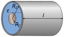
Цилиндрический конденсатор
Емкость цилиндрического конденсатора равняется:
C=2πεε0llnR2R1, где l — высота цилиндров, R1 и R2 — радиусы обкладок. Данный вид конденсатора имеет две соосные поверхности проводящих цилиндрических поверхности, как показано на рисунке 3.

Рисунок 3
Важной характеристикой конденсаторов считается пробивное напряжение — напряжение, при котором происходит электрический разряд через слой диэлектрика.
Umax находится от зависимости от толщины слоя и свойств диэлектрика, конфигурации конденсатора.
Электроемкость плоского конденсатора. Формулы
Кроме отдельных конденсаторов используются их соединения. Наличие параллельного соединения конденсаторов применяют для увеличения его емкости. Тогда поиск результирующей емкости соединения сводится к записи суммы Ci, где Ci- это емкость конденсатора с номером i:
C=∑i=1NCi.
При последовательном соединении конденсаторов суммарная емкость соединения всегда будет по значению меньше, чем минимальная любого конденсатора, входящего в систему. Для расчета результирующей емкости следует сложить величины, обратные к емкостям отдельных конденсаторов:
Произвести вычисление емкости плоского конденсатора при известной площади обкладок
1 см2 с расстоянием между ними 1 мм. Пространство между обкладками находится в вакууме.
Решение
Чтобы рассчитать электроемкость конденсатора, применяется формула:
C=εε0Sd.
Значения:
ε=1, ε0=8,85·10-12 Фм;S=1 см2=10-4 м2;d=1 мм=10-3 м.
Подставим числовые выражения и вычислим:
C=8,85·10-12·10-410-3=8,85·10-13 (Ф).
Ответ: C≈0,9 пФ.
Найти напряженность электростатического поля у сферического конденсатора на расстоянии x=1 см=10-2 м от поверхности внутренней обкладки при внутреннем радиусе обкладки, равном R1=1 см=10-2 м, внешнем – R2=3 см=3·10-2 м. Значение напряжения — 103 В.
Решение
Производящая заряженная сфера создает напряженность поля. Его значение вычисляется по формуле:
E=14πεε0qr2, где q обозначают заряд внутренней сферы, r=R1+x — расстояние от центра сферы.
Нахождение заряда предполагает применение определения емкости конденсатора С:
q=CU.
Для сферического конденсатора предусмотрена формула вида
C=4πεε0R1R2R2-R1 с радиусами обкладок R1 и R2.
Производим подстановку выражений для получения искомой напряженности:
E=14πεε0U(x+R1)24πεε0R1R2R2-R1=U(x+R1)2R1R2R2-R1.
Данные представлены в системе СИ, поэтому достаточно заменить буквы числовыми выражениями:
E=103(1+1)2·10-4·10-2·3·10-23·10-2-10-2=3·10-18·10-6=3,45·104 Вм.
Ответ: E=3,45·104 Вм.
Общие сведения
Радиокомпоненты, накапливающие электрический заряд, получили широкое применение в различных электронных устройствах. Чтобы понять их принцип работы, необходимо рассмотреть физическую природу емкости, т. е. способность проводника накапливать заряженные частицы.
Для ее демонстрации необходимо выполнить простейший опыт, который заключается в снятии шерстяного свитера. При этом возникает эффект статического (накопленного) электричества, поскольку электризуются тело и одежда. Чтобы разрядить их, необходимо предоставить выход для тока. Это достигается прикосновение к другому человеку или металлическому предмету. Опыт можно выполнить в темноте.
При этом будет виден разряд. Однако это не все, чем можно удивить начинающего радиолюбителя. Для начала следует понять физический смысл величины электроемкости.
Физический смысл
Физический смысл электрической емкости заключается в способности тел накапливать электрозаряд под воздействием электромагнитного поля. Чтобы понять принцип его накапливания, необходимо привести более упрощенный пример — цистерну для воды. Если она пустая, то обладает только относительной или теоретической единицей объема.
По мере ее заполнения жидкостью появляется абсолютный (фактический) объем. Если цистерна имеет форму цилиндра, то он эквивалентен произведению площади поперечного сечения на высоту. Следовательно, при полном ее заполнении показатель емкости будет максимальным.
Далее нужно вернуться к обыкновенному проводнику. Под воздействием электромагнитного поля происходит заряд протонов и электронов. Последние начинают двигаться по физическому телу. Для демонстрации этого процесса нужно провести опыт, демонстрирующий накопление заряда. Для этого потребуются следующие компоненты:
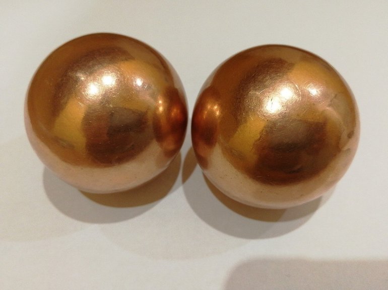
- Два медных шара (сферы).
- Соединительные провода.
- Выключатель.
- Источник питания 9 В.
После того как схема будет собрана, нужно пометить провода, идущие к шарам. Например, левый — «минус», а правый — «плюс». Далее требуется подключить источник в схему, соблюдая полярность, т. е. + к +, а — к -. Затем привести систему в действие, замкнув ключ (выключатель).
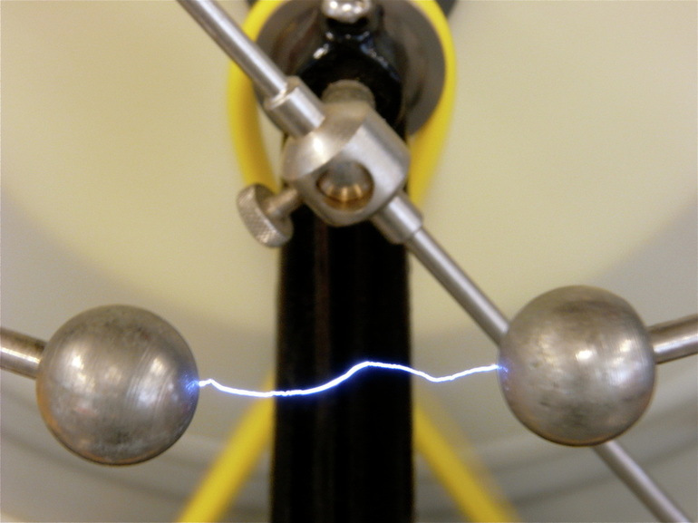
В этот момент между шарами будет образована разность потенциалов, которая приведет к генерации электромагнитного поля.
После отключения от источника питания между ними будет сохранен заряд. Он будет прямо пропорционален площади поперечного сечения электрода (шарика) и напряжению, а также обратно пропорционален расстоянию между шарами.
Иными словами, при увеличении напряжения и уменьшении расстояния произойдет стремительный рост электромагнитной составляющей (напряженности). Кроме того, на шарах будут генерироваться отрицательный и положительный заряды. Если напряжение увеличить в два раза, то и заряд (обозначается литерой q) тоже увеличится в два раза.
Следует отметить, что q шаров еще зависит от среды между ними, т. е. сила взаимодействия (Fq) уменьшается или увеличивается. Например, если между шарами находится вакуум, то Fq будет иметь одно значение. Когда между элементами находится нейлон, то Fq увеличится ровно в три раза.
Далее нужно ознакомиться с единицей измерения емкости и соотношением для ее нахождения.
Единица измерения
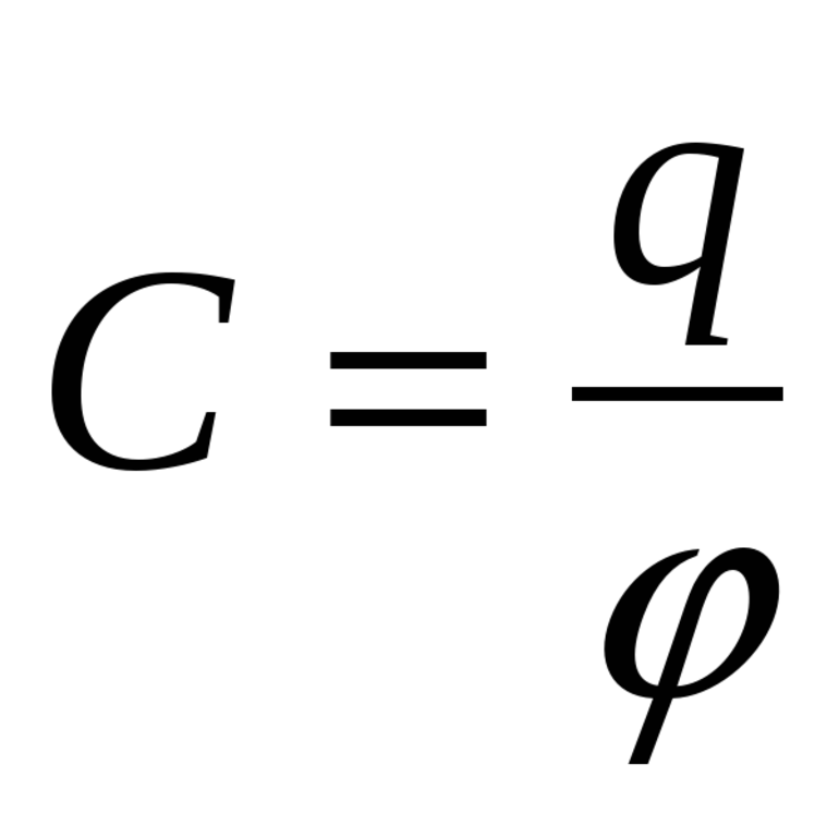
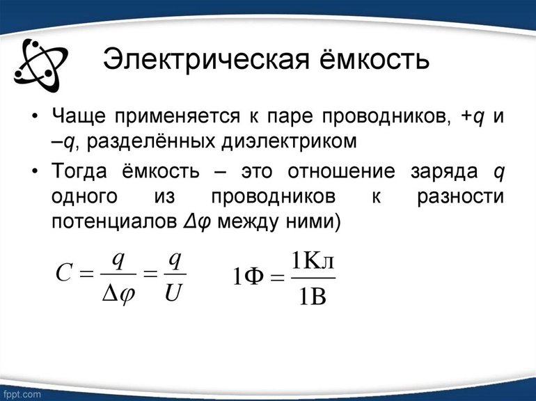
Характеристика тел способных проводить, накапливать и удерживать электрический заряд, измеряемая отношением величины заряда уединенного проводника к потенциалу, является электрической емкостью (обозначение литерой «С»). Ее можно найти по следующей формуле (математическая запись предыдущей формулировки): C=q/f, где q — заряд и f — потенциал.
Следует отметить, что соотношение позволяет установить единицу измерения емкости проводника, т. е. С= Кл/В. В международной системе она называется фарадой (Ф). Однако в электрических схемах такой показатель может просто вывести из строя радиокомпоненты, поскольку является очень большим. В этом случае применяются элементы со значительно меньшими величинами, т. е. мкФ (1 мкФ=10^(-6)Ф), нФ (1 нФ=10^(-9)Ф) и т. д.
Информация о конденсаторах
Конденсатор — радиодеталь, предназначенная для накопления электрической энергии. Они бывают двух видов:
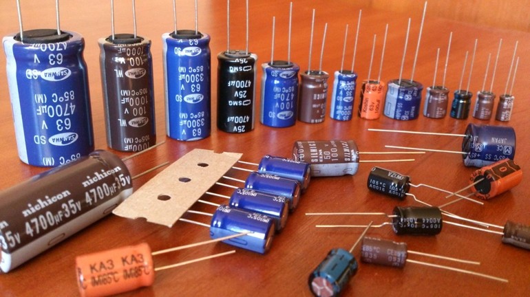
- Постоянными.
- Переменными.
Первые обладают постоянным значением электрической емкости, которая не изменяется с течением времени или в результате воздействия любого характера (механическое, термическое, электрическое). Как правило, при проектировании электрической цепи необходимо точно рассчитывать значение радиоэлемента.
Ко второй группе относятся устройства, обладающие переменной емкостной характеристикой. Регулировка осуществляется механическим или электрическим способом. В первом случае у конденсатора вынесена специальная ручка, предназначенная для уменьшения или увеличения емкостей. Они в основном применяются в радиоакустике для настройки контуров.
Последние представляют систему, состоящую из катушки индуктивности и переменного конденсатора.
Элементы с электронной регулировкой называются варисторами. Их емкость зависит от поданной на них величины напряжения. Однако конденсаторы по типу подключаемого тока также классифицируются на две группы. К ним относятся следующие:
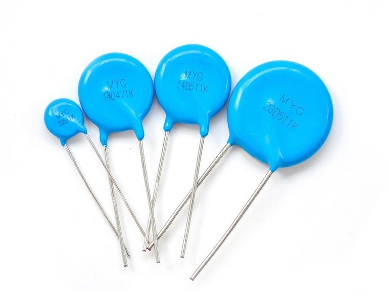
- Переменные.
- Электролитические (постоянная составляющая).
Первые в основном выполняют роль фильтров, которые поглощают различные колебания волны переменного тока, влияющие пагубно на устройства. Кроме того, для компенсации полного импеданса в сети (совокупность активного и реактивного сопротивлений) иногда необходимо уменьшать значение емкостного сопротивления. Последнее негативно влияет на электродвигатели, трансформаторы и другие устройства, состоящие из элементов индуктивности.
Однако наиболее часто применяются конденсаторы электролитического типа. Это связано с тем, что практически вся аппаратура питается только постоянным током. Для накопления заряда необходимо использовать элементы для постоянного тока.
Следует отметить, что при их монтаже в электрическую схему необходимо строго соблюдать полярность. В противном случае радиоэлемент может взорваться. При этом может выйти из строя самые незащищенные и дорогостоящие элементы (транзисторы, симисторы, интегральные микросхемы и т. д. ).
Конструкция элемента
Конденсатор — радиоэлемент, состоящий из нескольких компонентов. К ним относятся следующие:
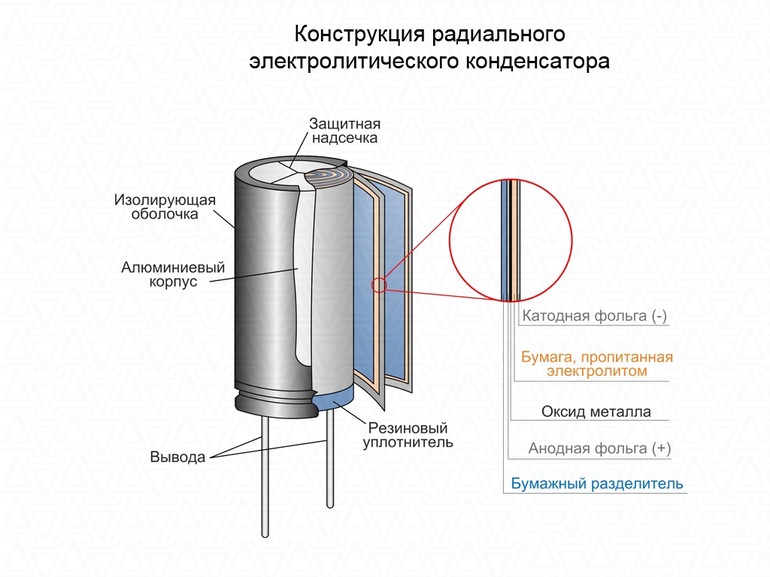
- Корпус.
- Два электрода.
- Прокладка.
- Выводы.
Корпус предназначен для защиты электродов от механических воздействий и электрических помех, влияющих на емкость. Кроме того, на него наносится специальная маркировка, по которой можно получить информацию о технических характеристиках устройства.
Для увеличения емкости два электрода изготавливаются из фольги. Последняя сматывается в виде цилиндра в два слоя, между которыми располагается диэлектрик — материал (прокладка), не пропускающий электроток. Для подключения в электрическую схему к электродам прикрепляются два вывода. Их называют «ножками».
Определение характеристик
Для использования конденсатора в цепи нужно знать его основные технические характеристики. К ним относятся следующие:
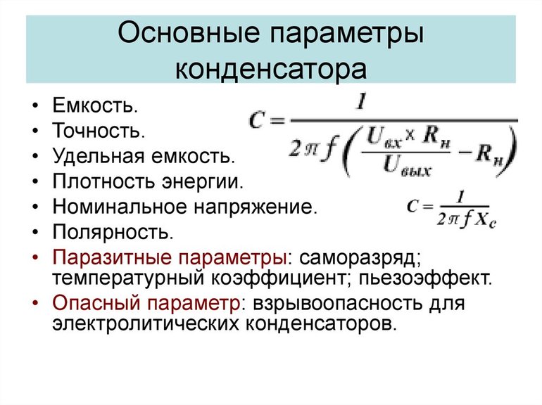
- Емкость.
- Напряжение пробоя.
Первая является основной, поскольку этот радиоэлемент используется для накопления заряда. Однако устройства, рассчитанные на низкие токи и напряжения, могут выйти из строя при повышенном параметре емкости. Например, компьютерная техника. В ней все рассчитано, и малейшее превышение заряда может не открыть необходимый транзистор.
Последний нужен для кодирования информации в нули и единицы.
Однако не во всех устройствах пристального внимания заслуживает параметр емкости. Иногда ключевой момент представлен напряжением пробоя. Например, в блоках питания конденсаторы используются в качестве фильтрующих элементов. Проектировщики радиоаппаратуры используют только расчетные значения характеристик.
Например, со сглаживанием пульсаций тока после диодного моста легко справляется конденсатор емкостью 1000 мкФ и напряжением (U) 25 В. Однако допускается использовать радиодеталь с завышенными параметрами, т. е. С=2200 мкФ и U=50 В.
Этот подход улучшит схему, поскольку существенно «сгладит» пульсации, и не выйдет из строя при превышении величины напряжения пробоя.
Однако не во всех случаях можно определить характеристики конденсатора. Иногда маркировка может быть стерта. Она может измеряться при помощи специального прибора — мультиметра. Однако в нем должна поддерживаться эта функция. Этот способ обладает существенным недостатком — им невозможно измерять радиокомпоненты большой емкости, поскольку кроны будет недостаточно для полной зарядки элемента (источник питания мультиметра — крона).
Таким образом, каждый проводник электрического тока обладает емкостной характеристикой, способной накапливать электрический заряд. На этом принципе построены конденсаторы, без которых не будет работать ни одна современная аппаратура.
Одним из важных параметров, учитываемых в электрических цепях, является электрическая емкость – способность проводников накапливать заряды. Понятие емкости применяется как для уединенного проводника, так и для системы, состоящей из двух и более проводников. В частности, емкостью обладают конденсаторы, состоящие из двух металлических пластин, разделенных диэлектриком или электролитом.
Для накопления зарядов широко применяютсяаккумуляторы, используемые в качестве источников постоянного тока для питания различных устройств. Количественной характеристикой, определяющей время работы аккумулятора, является его электроемкость.
Определение
Если диэлектрик, например, эбонитовую палочку, наэлектризовать трением то электрические заряды сконцентрируются в местах соприкосновения с электризующим материалом. При этом, другой конец палочки можно насытить зарядами противоположно знака и такая наэлектризованность будет сохраняться.
Совсем по-другому ведут себя проводники, помещенные электрическое поле. Заряды распределяются по их поверхности, образуя некий электрический потенциал. Если поверхность ровная, как у палочки, то заряды распределятся равномерно. Под действием внешнего электрического поля в проводнике происходит такое распределение электронов, чтобы внутри его сохранялся баланс взаимной компенсации негативных и позитивных зарядов.
Внешнее электрическое поле притягивает электроны на поверхность проводника, компенсируя при этом положительные заряды ионов. По отношению к проводнику имеет место электростатическая индукция, а заряды на его поверхности называются индуцированными. При этом на концах проводника плотность зарядов будет несколько выше.
На металлическом шаре заряды распределяются равномерно по всей поверхности. Наличие полости любой конфигурации абсолютно не влияет на процесс распределения.
Однако, если проводник убрать из зоны действия поля, то его заряды перераспределятся таким образом, что он снова станет электрически нейтральным.
На рисунке 1 изображена схема заряженного разнополюсного диэлектрика и проводника, удалённого из зоны действия электростатического поля. Благодаря тому, что диэлектрик сохраняет полученные заряды, уединенный проводник восстановил свою нейтральность.

Интересное явление наблюдается с двумя проводниками, разделенными диэлектриком. Если одному из них сообщить положительный заряд, а другому – отрицательный, то после убирания источника электризации заряды на поверхности проводников сохранятся. Заряженные таким образом проводники обладают разностью потенциалов.
Заряды, накопившиеся на диэлектрике, уравновешивают внутренние взаимодействие в каждом из проводников, не позволяя им разрядиться. Величина заряда зависит от площади поверхности параллельных проводников и от свойства диэлектрика, расположенного между ними.
Свойство сохранять накопленный заряд называется электроемкостью. Точнее говоря, – это характеристика проводника, физическая величина определяющая меру его способности в накоплении электрического заряда.
Накопленное электричество можно снять с проводников путем короткого замыкания их или через нагрузку. С целью увеличения емкости на практике применяют параллельные пластины или же длинные полоски тонкой фольги, разделённой диэлектриком. Полоски сворачивают в тугой цилиндр для уменьшения объема. Такие конструкции называют конденсаторами.
На рисунке 2 изображена схема простейшего конденсатора с плоскими обкладками.

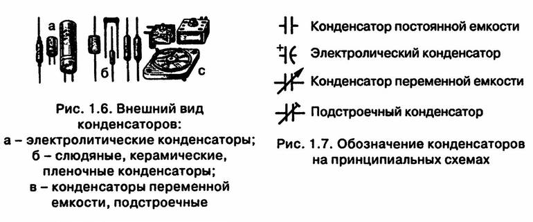
Существуют конденсаторы других типов:
- переменные;
- электролитические;
- оксидные;
- бумажные;
- комбинированные и другие.
Важной характеристикой конденсатора, как и других накопительных систем, является его электрическая емкость.
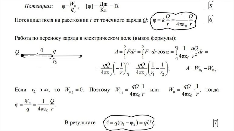
Формулы
На рисунке 3 наглядно показано формулы для определения емкости, в т. ч. и для сферы.

По отношению к конденсатору, для определения его емкости применяют формулу: C = q/U. То есть, эта величина прямо пропорциональна заряду одной из обкладок и обратно пропорциональна разнице потенциалов между обкладками (см. рис. 4).

О других способах определения ёмкости конденсатора читайте в нашей статье: https://www.asutpp.ru/kak-opredelit-emkost-kondensatora.html
Единицы измерения
За единицу измерения величины электроемкости принято фараду: 1 Ф = 1 Кл/1В. Поскольку фарада величина огромная, то для измерения емкости на практике она мало пригодна. Поэтому используют приставки:
- мили (м) = 10-3;
- микро (мк) = 10-6;
- нано (н) = 10-9;
- пико (пк) = 10-12;
Например, электрическая емкость 1 мкф = 0,000001 Ф. Параметр зависит от геометрических размеров, конфигурации проводника и материала диэлектрика.
Уединенный проводник и его емкость
Уединенным называют проводник, влиянием на который других элементов цепей можно пренебречь. Предполагается, что все другие проводники бесконечно удалены от него, а как известно, потенциал точки, бесконечно удаленной в пространстве, равен 0.
Электрическую емкость C уединенного проводника, определяют как количество электричества q, которое требуется для повышения электрического потенциала на 1 В: С = q/ϕ. Параметр не зависит от материала, из которого изготовлен проводник.
Конденсаторы постоянной и переменной емкости
Эра накопителей электричества началась с воздушных конденсаторов. Благодаря плоскому конденсатору с большой площадью обкладок физики смогли понять, как взаимная емкость регулируется площадями пластин, что позволило им создать конденсаторы с переменной емкостью (см. рис. 5).

Идея изменения емкости состояла в том, чтобы путем поворота плоской обкладки изменять площадь поверхности, которая располагается напротив другой пластины. Если обкладки располагались точно друг против друга, то напряженность поля между ними была максимальной. При смещении одной из пластин на некоторый угол, напряженность уменьшалась, что приводило к изменению емкости. Таким образом, можно было плавно управлять накопительной способностью конденсатора.
Детали с переменной емкостью нашли применение в первых радиоприемниках для поиска частоты нужной станции. Данный принцип используется по сегодняшний день в различных аналоговых электрических схемах.
Большую популярность приобрели электролитические конденсаторы. В качестве одной из обкладок у них используется электролит, обладающий высокими показателями диэлектрической проницаемости. Благодаря диэлектрическим свойствам электролитов такие конденсаторы обладают большими емкостями.
Главные их преимущества электролитического конденсатора:
- высокие
показатели емкости при малом объеме; - применение в
цепях с постоянным током.
Недостатки:
- необходимо соблюдать полярность;
- ограниченный срок службы;
- чувствительность к повышенным напряжениям.
Высокую электрическую прочность имеют плоские конденсаторы, у которых в качестве диэлектрического материала применяется керамика. Они используются в цепях с переменным током и выдерживают большие напряжения.
Сегодня промышленность поставляет на рынок множество конденсаторов различных типов, с высокими показателями проницаемости диэлектриков.

Аккумуляторы и электроемкость
Накопители электричества большой емкости (аккумуляторы) состоят из положительных и негативных пластин, погруженных в электролит. Во время зарядки часть атомов электролита распадается на ионы, которые оседают на пластине. Образуется разность потенциалов между пластинами, что является причиной возникновения ЭДС при подключении нагрузки.
С целью увеличения напряжения аккумуляторы последовательно соединяют в батареи. Разница потенциалов одной секции около 2 В. Для получения аккумулятора на 6 В необходимо создать батарею из трех секций, а на 12 В – батарею из 6 секций.
Для характеристики аккумуляторов (батарей) используются параметры:
- емкости;
- номинального напряжения;
- максимального тока разряда.
Единицей емкости аккумулятора является ампер-час (А*ч) или кратные ей миллиампер-часы (мА*ч). Емкость аккумулятора зависит от площади пластин. Увеличить емкость можно путем параллельного подключения нескольких секций, но такой способ почти не применяется, так как проще и надежнее создать аккумулятор с большими пластинами.
электрическая ёмкость
- электрическая ёмкость
- электри́ческая ёмкость
(С), величина, характеризующая способность проводника удерживать электрический заряд. Для уединённого проводника С = Q/φ, где Q — заряд проводника, φ — его потенциал. Электрическая ёмкость конденсатора С = Q/(φ1 — φ2), где Q — абсолютная величина заряда одной из обкладок, φ1 — φ2 — разность потенциалов между обкладками (φ1>φ2). Измеряется в системе СГС в см, в СИ — в фарадах.
* * *
ЭЛЕКТРИЧЕСКАЯ ЕМКОСТЬ
ЭЛЕКТРИ́ЧЕСКАЯ ЕМКОСТЬ (С), характеристика проводящего тела, мера его способности накапливать электрический заряд (см. ЭЛЕКТРИЧЕСКИЙ ЗАРЯД).
Когда увеличивается заряд проводника, то прямо пропорционально заряду будет возрастать его потенциал (см. ПОТЕНЦИАЛ (в физике)). Это справедливо для проводников любой геометрической формы. Отношение заряда проводника к его потенциалу не зависит от величины заряда, находящегося на проводнике, и определяются свойствами самого проводника, а также среды, в которой он находится. Характеристикой электрических свойств проводника, определяющей возможность накопления зарядов на данном проводнике, является электрическая емкость С.
Так как заряду q проводника пропорционален потенциал j(отсчитываемый от нулевого уровня на бесконечности), то электрическая емкость С уединенного проводника равна отношению заряда проводника к потенциалу и определяется отношением:
С = q/j.
Таким образом, чем больше электрическая емкость, тем больший заряд может накопить проводник, имеющий данный потенциал.
Численно электрическая емкость С равна заряду q, который необходимо сообщить уединенному телу для изменения его потенциала на единицу.
Единица электроемкости в системе СИ — фарад (см. ФАРАД). 1 Ф — это емкость такого уединенного проводника, потенциал которого изменяется на 1 В (вольт (см. ВОЛЬТ)) при сообщении ему заряда 1 Кл (кулон (см. КУЛОН (единица количества электричества))).
В системе единиц СГСЕ электрическая емкость измеряется в сантиметрах.
1 Ф = 9.1011 см.
Емкость уединенного шара радиусом R, равна:
С = 4pоR.
Поэтому в системе СГСЕ электрическая емкость проводящего шара в вакууме равна его радиусу. Емкостью 1 Ф обладает шар, радиус которого равен 9.106км. Если считать Землю уединенным проводником, то ее электрическая емкость составляла бы порядка 0,7мФ.
В общем случае электрическая емкость геометрически подобных проводящих тел пропорциональна их размерам. Емкость зависит от геометрических размеров и формы проводников, взаимного расположения проводников и диэлектрической проницаемости, но не зависит от материала проводника.
Наличие вблизи проводника других тел изменяет его электрическую емкость, так как потенциал проводника зависит и от электрических полей, создаваемых наведенными в окружающих телах зарядами вследствие явления электростатической индукции (см. ЭЛЕКТРОСТАТИЧЕСКАЯ ИНДУКЦИЯ).
Понятие электрической емкости относится не только к одному проводнику, но и к системе проводников, в частности к системе двух проводников, разделенных тонким слоем диэлектрика — конденсатору электрическому (см. КОНДЕНСАТОР (электрический)). Конденсаторы используют для получения нужных величин электрической емкости в технике. Емкость конденсатора характеризует не отдельную пластину, а систему двух пластин (проводников) в их взаимном расположении друг к другу. Электрическая емкость всегда характеризует систему из двух тел, между которыми установилась разность потенциалов (так как физический смысл имеет только разность потенциалов между двумя точками (см Потенциал электростатический (см. ПОТЕНЦИАЛ ЭЛЕКТРОСТАТИЧЕСКИЙ)). Электроемкость конденсатора (взаимная емкость его обкладок), заряженных соответственно зарядами +q и –q, это физическая величина, равная отношению заряда одного из проводников к разности потенциалов между этим проводниками. Электрическая емкость конденсатора практически не зависит от наличия окружающих тел и может достигать очень большой величины при малых геометрических размерах конденсаторов.
Все элементы и устройства, применяемые в электрических цепях различного назначения (трансформаторы, электронные приборы) также обладают электрической емкостью, влияние которой в некоторых режимах может быть существенным.
Энциклопедический словарь.
2009.
Полезное
Смотреть что такое «электрическая ёмкость» в других словарях:
-
ЭЛЕКТРИЧЕСКАЯ ЁМКОСТЬ — параметр, характеризующий физ. способность проводника, совокупности проводников или электрического конденсатора (см. (2)) удерживать электрический заряд, равный отношению заряда, который сообщается уединённому проводнику, к его потенциалу.… … Большая политехническая энциклопедия
-
Электрическая ёмкость — Электрическая емкость ЭЛЕКТРИЧЕСКАЯ ЁМКОСТЬ (C), величина, характеризующая способность проводника удерживать электрический заряд. Для уединенного проводника C=Q/j, где Q заряд проводника, j его потенциал. Электрическая емкость конденсатора… … Иллюстрированный энциклопедический словарь
-
ЭЛЕКТРИЧЕСКАЯ ЁМКОСТЬ — характеристика проводника, количеств. мера его способности удерживать электрич. заряд. В электростатич. поле все точки поверхности проводника имеют один и тот же потенциал. Потенциал j (отсчитываемый от нулевого уровня на бесконечности) пропорц.… … Физическая энциклопедия
-
электрическая ёмкость — — [А.С.Гольдберг. Англо русский энергетический словарь. 2006 г.] Тематики энергетика в целом EN permitance … Справочник технического переводчика
-
Электрическая ёмкость — Классическая электродинамика … Википедия
-
электрическая ёмкость — elektrinė talpa statusas T sritis fizika atitikmenys: angl. electric capacitance; electrical capacitance vok. elektrische Kapazität, f rus. электрическая ёмкость, f pranc. capacité électrique, f … Fizikos terminų žodynas
-
Электрическая ёмкость — характеристика проводника, количественная мера его способности удерживать электрический заряд. В электростатическом поле все точки проводника имеют один и тот же потенциал φ. Потенциал φ (отсчитываемый от нулевого уровня на бесконечности) … Большая советская энциклопедия
-
ЭЛЕКТРИЧЕСКАЯ ЁМКОСТЬ — электрич. хар ка проводника или системы проводников. Э. ё. уединённого проводника наз. физ. величина С, равная отношению электрич. заряда, к рый сообщается уединённому проводнику, к его электрич. потенциалу: С = Q/ф. где Q и ф заряд и потенциал… … Большой энциклопедический политехнический словарь
-
ЭЛЕКТРИЧЕСКАЯ ЁМКОСТЬ — (С), величина, характеризующая способность проводника удерживать электрич. заряд. Для уединённого проводника С= Q/ф, где Q заряд проводника, ф его потенциал. Э.ё. конденсатора С = Q/(ф1 ф2), где Q абс. величина заряда одной из обкладок, ф1 ф2… … Естествознание. Энциклопедический словарь
-
электрическая ёмкость — физ. Количественная мера способности тела удерживать электрический заряд … Словарь многих выражений
Мы все знаем об электрическом токе, проводимости и сопротивлении. Но емкость является еще одной важной частью понимания концепции электричества. Возможно, вы слышали, что ничто не может хранить электричество. Однако это не так — конденсаторы способны накапливать электрический заряд. Давайте подробнее рассмотрим концепцию конденсаторов и емкости. Начнем с конденсатора.
Конденсатор образован двумя обращенными друг к другу проводниками, между которыми вставлен диэлектрик, то есть изолирующий материал. Эти два проводника называются обкладками конденсатора.
Главной характеристикой конденсаторов является величина емкости.
Емкость конденсатора — формула
Определение
Емкость конденсатора — это ничто иное, как умение конденсатора накапливать энергию в виде электрического заряда. Другими словами, емкость — это запоминающая способность конденсатора. Измеряется емкость в фарадах.
Емкость может быть рассчитана, когда известны заряд Q и напряжение V конденсатора:

Емкость используется для описания того, сколько заряда может удерживать любой проводник. Он представляет собой отношение заряда к приложенному потенциалу.
Любой объект, который может быть электрически заряжен, показывает емкость. Конденсатор с двумя параллельными пластинами — это обычная форма накопителя энергии. Емкость отображается параллельным расположением пластин и определяется с точки зрения накопления заряда. Когда конденсатор заряжен полностью, между его пластинами имеется разность потенциалов, и чем больше площадь пластин и чем меньше расстояние между ними, тем больше будет заряд конденсатора и тем больше будет его Емкость.
Если конденсаторы соединены последовательно, формула емкости выражается следующим образом:

Если конденсаторы подключены параллельно, формула емкости выражается следующим образом:

Где C1, C2, C3 ……. Cn — конденсаторы, а емкость выражается в фарадах.
Примеры решения:
Пример 1
Определите емкость конденсатора, если течет 5 кулонов заряда и приложен потенциал 2 В.
Решение
Приведенные параметры
Заряд Q составляет 5 C,
Приложенное напряжение V равно 2 В.
Формула емкости определяется как
C=Q/V
= 5/2
= 2,5 F
Пример 2
Определите емкость, если подключены конденсаторы 6 Ф и 5 Ф.
a) последовательно;
b) параллельно
Решение
Формула последовательной емкости определяется как
Cs = 1 / C1 + 1 / C2
= C1 + C2 / C1C2
= 6 + 5/30
Cs = 0,367 F
Емкость в параллельной формуле определяется как
Ср = С1 + С2
= 6 + 5
Cp = 11 F
Различают три вида конденсаторов:
- Конденсатор плоский;
- Конденсатор цилиндрический
- Конденсатор сферический.
Конденсатор плоский
Данный конденсатор образован двумя металлическими пластинами, которые мы называем A и B, расположенными на расстоянии d.

Две проводящие пластины A и B являются пластинами конденсатора, d — их расстояние, более того, поскольку две пластины параллельны, их поверхности равны.

Мы знаем, что внутри двух поверхностей электрическое поле однородно, а снаружи равно нулю

Рассчитываем разность потенциалов между двумя пластинами

Как только разность потенциалов известна, мы можем рассчитать емкость плоского конденсатора.

Заменим найденную ранее разность потенциалов

Конденсатор цилиндрический
Конденсатор используется для хранения большого количества электрического тока в небольшом пространстве. Цилиндрический конденсатор включает полый или сплошной цилиндрический проводник, окруженный концентрическим полым сферическим цилиндром. Конденсаторы широко используются в электродвигателях, мельницах, электрических соковыжималках и других электрических инструментах. Разность потенциалов между конденсаторами различна. Существует множество электрических цепей, в которых конденсаторы должны быть сгруппированы соответствующим образом, чтобы получить желаемую емкость. Есть два общих режима, включая конденсаторы, включенные последовательно, и конденсаторы, подключенные параллельно. Единица измерения емкости — Фарад (Ф).
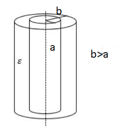
Его часто используют для хранения электрического заряда. Цилиндрический конденсатор — это тип конденсатора, который имеет форму цилиндра, имеющую внутренний радиус как a и внешний радиус как b.
Формула для цилиндрического конденсатора:

C = емкость цилиндра
L = длина цилиндра
a = внутренний радиус цилиндра,
b = внешний радиус
εₒ= диэлектрическая проницаемость свободного пространства (8.85×10ˉ¹²)
Пример
Цилиндрический конденсатор длиной 8 см состоит из двух колец с внутренним радиусом 3 см и внешним радиусом 6 см. Найдите емкость конденсатора.
Дано:
Длина L = 8 см
внутренний радиус a = 3 см
внешний радиус b = 6 см
Решение
Формула для конденсатора цилиндрического:

Конденсатор сферический
Данный конденсатор состоит из сплошного или полого сферического проводника, окруженного другой полой концентрической сферической формой другого радиуса.
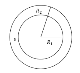
Формула для определения емкости сферического конденсатора

Где,
C = емкость
Q = заряд
V = напряжение
r 1 = внутренний радиус
r 2 = внешний радиус
ε 0 = диэлектрический потенциал (8,85 x 10⁻¹² Ф / м)
Значение емкости двух разных конденсаторов может быть одинаковым, а номинальное напряжение двух конденсаторов может быть разным. Возьмем два конденсатора — один с малым номинальным напряжением, а другой с высоким. Если мы заменим конденсатор с меньшим номинальным напряжением на конденсатор с более высоким номинальным напряжением, то получится конденсатор меньшего размера. Это может произойти из-за неожиданного повышения напряжения.

Нет времени решать самому?
Наши эксперты помогут!
Влияние диэлектрика на емкость
Плотности поверхностного заряда равны σ p и — σ p. Когда мы полностью помещаем диэлектрик между двумя пластинами конденсатора, его диэлектрическая проницаемость увеличивается по сравнению с вакуумным значением.
Внутри конденсатора следующее электрическое поле:

Следовательно, мы имеем:

а именно:

Ɛ — диэлектрическая проницаемость. Разность потенциалов между пластинами задаются

Для линейных диэлектриков:

Где k — диэлектрическая проницаемость вещества, K = 1.

Электрическое поле между пластинами конденсатора прямо пропорционально емкости конденсатора. Напряжение электрического поля снижается из-за наличия диэлектрика. Если общий заряд на пластинах поддерживается постоянным, то уменьшается разность потенциалов на пластинах конденсатора. Таким образом, диэлектрик увеличивает емкость конденсатора.