This article is about the history of the reciprocating-type steam engine. For the parallel development of turbine-type engines, see Steam turbine.

The 1698 Savery Steam Pump — the first commercially successful steam powered device, built by Thomas Savery
The first recorded rudimentary steam engine was the aeolipile mentioned by Vitruvius between 30 and 15 BC and, described by Heron of Alexandria in 1st-century Roman Egypt.[1] Several steam-powered devices were later experimented with or proposed, such as Taqi al-Din’s steam jack, a steam turbine in 16th-century Ottoman Egypt, and Thomas Savery’s steam pump in 17th-century England. In 1712, Thomas Newcomen’s atmospheric engine became the first commercially successful engine using the principle of the piston and cylinder, which was the fundamental type of steam engine used until the early 20th century. The steam engine was used to pump water out of coal mines.
During the Industrial Revolution, steam engines started to replace water and wind power, and eventually became the dominant source of power in the late 19th century and remaining so into the early decades of the 20th century, when the more efficient steam turbine and the internal combustion engine resulted in the rapid replacement of the steam engines. The steam turbine has become the most common method by which electrical power generators are driven.[2] Investigations are being made into the practicalities of reviving the reciprocating steam engine as the basis for the new wave of advanced steam technology.
Precursors[edit]
Early uses of steam power[edit]
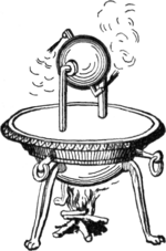
The earliest known rudimentary steam engine and reaction steam turbine, the aeolipile, is described by a mathematician and engineer named Heron of Alexandria in 1st century Roman Egypt, as recorded in his manuscript Spiritalia seu Pneumatica.[3][4] The same device was also mentioned by Vitruvius in De Architectura about 100 years earlier. Steam ejected tangentially from nozzles caused a pivoted ball to rotate. Its thermal efficiency was low. This suggests that the conversion of steam pressure into mechanical movement was known in Roman Egypt in the 1st century. Heron also devised a machine that used air heated in an altar fire to displace a quantity of water from a closed vessel. The weight of the water was made to pull a hidden rope to operate temple doors.[4][5] Some historians have conflated the two inventions to assert, incorrectly, that the aeolipile was capable of useful work.[citation needed]
According to William of Malmesbury, in 1125, Reims was home to a church that had an organ powered by air escaping from compression «by heated water», apparently designed and constructed by professor Gerbertus.[4][6]
Among the papers of Leonardo da Vinci dating to the late 15th century is the design for a steam-powered cannon called the Architonnerre, which works by the sudden influx of hot water into a sealed, red-hot cannon.[7]
A rudimentary impact steam turbine was described in 1551 by Taqi al-Din, a philosopher, astronomer and engineer in 16th century Ottoman Egypt, who described a method for rotating a spit by means of a jet of steam playing on rotary vanes around the periphery of a wheel. A similar device for rotating a spit was also later described by John Wilkins in 1648.[8] These devices were then called «mills» but are now known as steam jacks. Another similar rudimentary steam turbine is shown by Giovanni Branca, an Italian engineer, in 1629 for turning a cylindrical escapement device that alternately lifted and let fall a pair of pestles working in mortars.[9] The steam flow of these early steam turbines, however, was not concentrated and most of its energy was dissipated in all directions. This would have led to a great waste of energy and so they were never seriously considered for industrial use.
In 1605, French mathematician Florence Rivault in his treatise on artillery wrote on his discovery that water, if confined in a bombshell and heated, would explode the shells.[10]
In 1606, the Spaniard Jerónimo de Ayanz y Beaumont demonstrated and was granted a patent for a steam-powered water pump. The pump was successfully used to drain the inundated mines of Guadalcanal, Spain.[11]
Development of the commercial steam engine[edit]
«The discoveries that, when brought together by Thomas Newcomen in 1712, resulted in the steam engine were:»[12]
- The concept of a vacuum (i.e. a reduction in pressure below ambient)
- The concept of pressure
- Techniques for creating a vacuum
- A means of generating steam
- The piston and cylinder
In 1643, Evangelista Torricelli conducted experiments on suction lift water pumps to test their limits, which was about 32 feet. (Atmospheric pressure is 32.9 feet or 10.03 meters. Vapor pressure of water lowers theoretical lift height.) He devised an experiment using a tube filled with mercury and inverted in a bowl of mercury (a barometer) and observed an empty space above the column of mercury, which he theorized contained nothing, that is, a vacuum.[13]
Influenced by Torricelli, Otto von Guericke invented a vacuum pump by modifying an air pump used for pressurizing an air gun. Guericke put on a demonstration in 1654 in Magdeburg, Germany, where he was mayor. Two copper hemispheres were fitted together and air was pumped out. Weights strapped to the hemispheres could not pull them apart until the air valve was opened. The experiment was repeated in 1656 using two teams of 8 horses each, which could not separate the Magdeburg hemispheres.[13]
Gaspar Schott was the first to describe the hemisphere experiment in his Mechanica Hydraulico-Pneumatica (1657).[13]
After reading Schott’s book, Robert Boyle built an improved vacuum pump and conducted related experiments.[13]
Denis Papin became interested in using a vacuum to generate motive power while working with Christiaan Huygens and Gottfried Leibniz in Paris in 1663. Papin worked for Robert Boyle from 1676 to 1679, publishing an account of his work in Continuation of New Experiments (1680) and gave a presentation to Royal Society in 1689. From 1690 on Papin began experimenting with a piston to produce power with steam, building model steam engines. He experimented with atmospheric and pressure steam engines, publishing his results in 1707.[13]
In 1663, Edward Somerset, 2nd Marquess of Worcester published a book of 100 inventions which described a method for raising water between floors employing a similar principle to that of a coffee percolator. His system was the first to separate the boiler (a heated cannon barrel) from the pumping action. Water was admitted into a reinforced barrel from a cistern, and then a valve was opened to admit steam from a separate boiler. The pressure built over the top of the water, driving it up a pipe.[14] He installed his steam-powered device on the wall of the Great Tower at Raglan Castle to supply water through the tower. The grooves in the wall where the engine was installed were still to be seen in the 19th century. However, no one was prepared to risk money for such a revolutionary concept, and without backers the machine remained undeveloped.[13][15]
Samuel Morland, a mathematician and inventor who worked on pumps, left notes at the Vauxhall Ordinance Office on a steam pump design that Thomas Savery read. In 1698 Savery built a steam pump called «The Miner’s Friend.» It employed both vacuum and pressure. These were used for low horsepower service for a number of years.[13]
Thomas Newcomen was a merchant who dealt in cast iron goods. Newcomen’s engine was based on the piston and cylinder design proposed by Papin. In Newcomen’s engine steam was condensed by water sprayed inside the cylinder, causing atmospheric pressure to move the piston. Newcomen’s first engine installed for pumping in a mine in 1712 at Dudley Castle in Staffordshire.[13]
Cylinders[edit]
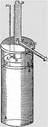
Denis Papin’s design for a piston-and-cylinder engine, 1680.
Denis Papin (22 August 1647 – c. 1712) was a French physicist, mathematician and inventor, best known for his pioneering invention of the steam digester, the forerunner of the pressure cooker. In the mid-1670s Papin collaborated with the Dutch physicist Christiaan Huygens on an engine which drove out the air from a cylinder by exploding gunpowder inside it. Realising the incompleteness of the vacuum produced by this means and on moving to England in 1680, Papin devised a version of the same cylinder that obtained a more complete vacuum from boiling water and then allowing the steam to condense; in this way he was able to raise weights by attaching the end of the piston to a rope passing over a pulley. As a demonstration model, the system worked, but in order to repeat the process, the whole apparatus had to be dismantled and reassembled. Papin quickly saw that to make an automatic cycle the steam would have to be generated separately in a boiler; however, he did not take the project further. Papin also designed a paddle boat driven by a jet playing on a mill-wheel in a combination of Taqi al Din and Savery’s conceptions and he is also credited with a number of significant devices such as the safety valve. Papin’s years of research into the problems of harnessing steam was to play a key part in the development of the first successful industrial engines that soon followed his death.
Savery steam pump[edit]
The first steam engine to be applied industrially was the «fire-engine» or «Miner’s Friend», designed by Thomas Savery in 1698. This was a pistonless steam pump, similar to the one developed by Worcester. Savery made two key contributions that greatly improved the practicality of the design. First, in order to allow the water supply to be placed below the engine, he used condensed steam to produce a partial vacuum in the pumping reservoir (the barrel in Worcester’s example), and using that to pull the water upward. Secondly, in order to rapidly cool the steam to produce the vacuum, he ran cold water over the reservoir.
Operation required several valves; at the start of a cycle, when the reservoir was empty, a valve would be opened to admit steam. This valve would be closed to seal the reservoir, and the cooling water valve would be opened to condense the steam and create a partial vacuum. A supply valve would then be opened, pulling water upward into the reservoir; the typical engine could pull water up to 20 feet.[16] This was then closed, and the steam valve reopened, building pressure over the water and pumping it upward, as in the Worcester design. This cycle essentially doubled the distance that water could be pumped for any given pressure of steam, and production examples raised water about 40 feet.[16]
Savery’s engine solved a problem that had only recently become a serious one; raising water out of the mines in southern England as they reached greater depths. Savery’s engine was somewhat less efficient than Newcomen’s, but this was compensated for by the fact that the separate pump used by the Newcomen engine was inefficient, giving the two engines roughly the same efficiency of 6 million foot pounds per bushel of coal (less than 1%).[17] Nor was the Savery engine very safe because part of its cycle required steam under pressure supplied by a boiler, and given the technology of the period the pressure vessel could not be made strong enough and so was prone to explosion.[18] The explosion of one of his pumps at Broad Waters (near Wednesbury), about 1705, probably marks the end of attempts to exploit his invention.[19]
The Savery engine was less expensive than Newcomen’s and was produced in smaller sizes.[20] Some builders were manufacturing improved versions of the Savery engine until late in the 18th century.[17] Bento de Moura Portugal, FRS, introduced an ingenious improvement of Savery’s construction «to render it capable of working itself», as described by John Smeaton in the Philosophical Transactions published in 1751.[21]
Atmospheric condensing engines[edit]
Newcomen «atmospheric» engine[edit]

Engraving of Newcomen engine. This appears to be copied from a drawing in Desaguliers’ 1744 work: «A course of experimental philosophy», itself believed to have been a reversed copy of Henry Beighton’s engraving dated 1717, that may represent what is probably the second Newcomen engine erected around 1714 at Griff colliery, Warwickshire.[22]
It was Thomas Newcomen with his «atmospheric-engine» of 1712 who can be said to have brought together most of the essential elements established by Papin in order to develop the first practical steam engine for which there could be a commercial demand. This took the shape of a reciprocating beam engine installed at surface level driving a succession of pumps at one end of the beam. The engine, attached by chains from other end of the beam, worked on the atmospheric, or vacuum principle.[23]
Newcomen’s design used some elements of earlier concepts. Like the Savery design, Newcomen’s engine used steam, cooled with water, to create a vacuum. Unlike Savery’s pump, however, Newcomen used the vacuum to pull on a piston instead of pulling on water directly. The upper end of the cylinder was open to the atmospheric pressure, and when the vacuum formed, the atmospheric pressure above the piston pushed it down into the cylinder. The piston was lubricated and sealed by a trickle of water from the same cistern that supplied the cooling water. Further, to improve the cooling effect, he sprayed water directly into the cylinder.

The piston was attached by a chain to a large pivoted beam. When the piston pulled the beam, the other side of the beam was pulled upward. This end was attached to a rod that pulled on a series of conventional pump handles in the mine. At the end of this power stroke, the steam valve was reopened, and the weight of the pump rods pulled the beam down, lifting the piston and drawing steam into the cylinder again.
Using the piston and beam allowed the Newcomen engine to power pumps at different levels throughout the mine, as well as eliminating the need for any high-pressure steam. The entire system was isolated to a single building on the surface. Although inefficient and extremely heavy on coal (compared to later engines), these engines raised far greater volumes of water and from greater depths than had previously been possible.[18] Over 100 Newcomen engines were installed around England by 1735, and it is estimated that as many as 2,000 were in operation by 1800 (including Watt versions).
John Smeaton made numerous improvements to the Newcomen engine, notably the seals, and by improving these was able to almost triple their efficiency. He also preferred to use wheels instead of beams for transferring power from the cylinder, which made his engines more compact. Smeaton was the first to develop a rigorous theory of steam engine design of operation. He worked backward from the intended role to calculate the amount of power that would be needed for the task, the size and speed of a cylinder that would provide it, the size of boiler needed to feed it, and the amount of fuel it would consume. These were developed empirically after studying dozens of Newcomen engines in Cornwall and Newcastle, and building an experimental engine of his own at his home in Austhorpe in 1770. By the time the Watt engine was introduced only a few years later, Smeaton had built dozens of ever-larger engines into the 100 hp range.[24]
Watt’s separate condenser[edit]

Early Watt pumping engine.
While working at the University of Glasgow as an instrument maker and repairman in 1759, James Watt was introduced to the power of steam by Professor John Robison. Fascinated, Watt took to reading everything he could on the subject, and independently developed the concept of latent heat, only recently published by Joseph Black at the same university. When Watt learned that the University owned a small working model of a Newcomen engine, he pressed to have it returned from London where it was being unsuccessfully repaired. Watt repaired the machine, but found it was barely functional even when fully repaired.
After working with the design, Watt concluded that 80% of the steam used by the engine was wasted. Instead of providing motive force, it was instead being used to heat the cylinder. In the Newcomen design, every power stroke was started with a spray of cold water, which not only condensed the steam, but also cooled the walls of the cylinder. This heat had to be replaced before the cylinder would accept steam again. In the Newcomen engine the heat was supplied only by the steam, so when the steam valve was opened again the vast majority condensed on the cold walls as soon as it was admitted to the cylinder. It took a considerable amount of time and steam before the cylinder warmed back up and the steam started to fill it up.
Watt solved the problem of the water spray by removing the cold water to a different cylinder, placed beside the power cylinder. Once the induction stroke was complete a valve was opened between the two, and any steam that entered the cylinder would condense inside this cold cylinder. This would create a vacuum that would pull more of the steam into the cylinder, and so on until the steam was mostly condensed. The valve was then closed, and operation of the main cylinder continued as it would on a conventional Newcomen engine. As the power cylinder remained at operational temperature throughout, the system was ready for another stroke as soon as the piston was pulled back to the top. Maintaining the temperature was a jacket around the cylinder where steam was admitted. Watt produced a working model in 1765.
Convinced that this was a great advance, Watt entered into partnerships to provide venture capital while he worked on the design. Not content with this single improvement, Watt worked tirelessly on a series of other improvements to practically every part of the engine. Watt further improved the system by adding a small vacuum pump to pull the steam out of the cylinder into the condenser, further improving cycle times. A more radical change from the Newcomen design was closing off the top of the cylinder and introducing low-pressure steam above the piston. Now the power was not due to the difference of atmospheric pressure and the vacuum, but the pressure of the steam and the vacuum, a somewhat higher value. On the upward return stroke, the steam on top was transferred through a pipe to the underside of the piston ready to be condensed for the downward stroke. Sealing of the piston on a Newcomen engine had been achieved by maintaining a small quantity of water on its upper side. This was no longer possible in Watt’s engine due to the presence of the steam. Watt spent considerable effort to find a seal that worked, eventually obtained by using a mixture of tallow and oil. The piston rod also passed through a gland on the top cylinder cover sealed in a similar way.[25]
The piston sealing problem was due to having no way to produce a sufficiently round cylinder. Watt tried having cylinders bored from cast iron, but they were too out of round. Watt was forced to use a hammered iron cylinder.[26] The following quotation is from Roe (1916):
«When [John] Smeaton first saw the engine he reported to the Society of Engineers that ‘neither the tools nor the workmen existed who could manufacture such a complex machine with sufficient precision’ «[26]
Watt finally considered the design good enough to release in 1774, and the Watt engine was released to the market. As portions of the design could be easily fitted to existing Newcomen engines, there was no need to build an entirely new engine at the mines. Instead, Watt and his business partner Matthew Boulton licensed the improvements to engine operators, charging them a portion of the money they would save in reduced fuel costs. The design was wildly successful, and the Boulton and Watt company was formed to license the design and help new manufacturers build the engines. The two would later open the Soho Foundry to produce engines of their own.
In 1774, John Wilkinson invented a boring machine with the shaft holding the boring tool supported on both ends, extending through the cylinder, unlike the then used cantilevered borers. With this machine he was able to successfully bore the cylinder for Boulton and Watt’s first commercial engine in 1776.[26]
Watt never ceased improving his designs. This further improved the operating cycle speed, introduced governors, automatic valves, double-acting pistons, a variety of rotary power takeoffs and many other improvements. Watt’s technology enabled the widespread commercial use of stationary steam engines.[27]
Humphrey Gainsborough produced a model condensing steam engine in the 1760s, which he showed to Richard Lovell Edgeworth, a member of the Lunar Society. Gainsborough believed that Watt had used his ideas for the invention;[28] however, James Watt was not a member of the Lunar Society at this period and his many accounts explaining the succession of thought processes leading to the final design would tend to belie this story.
Power was still limited by the low pressure, the displacement of the cylinder, combustion and evaporation rates and condenser capacity. Maximum theoretical efficiency was limited by the relatively low temperature differential on either side of the piston; this meant that for a Watt engine to provide a usable amount of power, the first production engines had to be very large, and were thus expensive to build and install.
Watt double-acting and rotative engines[edit]
Watt developed a double-acting engine in which steam drove the piston in both directions, thereby increasing the engine speed and efficiency. The double-acting principle also significantly increased the output of a given physical sized engine.[29][30]
Boulton & Watt developed the reciprocating engine into the rotative type. Unlike the Newcomen engine, the Watt engine could operate smoothly enough to be connected to a drive shaft – via sun and planet gears – to provide rotary power along with double-acting condensing cylinders. The earliest example was built as a demonstrator and was installed in Boulton’s factory to work machines for lapping (polishing) buttons or similar. For this reason it was always known as the Lap Engine.[31][32] In early steam engines the piston is usually connected by a rod to a balanced beam, rather than directly to a flywheel, and these engines are therefore known as beam engines.
Early steam engines did not provide constant enough speed for critical operations such as cotton spinning. To control speed the engine was used to pump water for a water wheel, which powered the machinery.[33][34]
High-pressure engines[edit]
As the 18th century advanced, the call was for higher pressures; this was strongly resisted by Watt who used the monopoly his patent gave him to prevent others from building high-pressure engines and using them in vehicles. He mistrusted the boiler technology of the day, the way they were constructed and the strength of the materials used.
The important advantages of high-pressure engines were:
- They could be made much smaller than previously for a given power output. There was thus the potential for steam engines to be developed that were small and powerful enough to propel themselves and other objects. As a result, steam power for transportation now became a practicality in the form of ships and land vehicles, which revolutionised cargo businesses, travel, military strategy, and essentially every aspect of society.
- Because of their smaller size, they were much less expensive.
- They did not require the significant quantities of condenser cooling water needed by atmospheric engines.
- They could be designed to run at higher speeds, making them more suitable for powering machinery.
The disadvantages were:
- In the low-pressure range they were less efficient than condensing engines, especially if steam was not used expansively.
- They were more susceptible to boiler explosions.
The main difference between how high-pressure and low-pressure steam engines work is the source of the force that moves the piston. In the engines of Newcomen and Watt, it is the condensation of the steam that creates most of the pressure difference, causing atmospheric pressure (Newcomen) and low-pressure steam, seldom more than 7 psi boiler pressure,[35] plus condenser vacuum[36] (Watt), to move the piston. In a high-pressure engine, most of the pressure difference is provided by the high-pressure steam from the boiler; the low-pressure side of the piston may be at atmospheric pressure or connected to the condenser pressure. Newcomen’s indicator diagram, almost all below the atmospheric line, would see a revival nearly 200 years later with the low pressure cylinder of triple expansion engines contributing about 20% of the engine power, again almost completely below the atmospheric line.[37]
The first known advocate of «strong steam» was Jacob Leupold in his scheme for an engine that appeared in encyclopaedic works from c. 1725. Various projects for steam propelled boats and vehicles also appeared throughout the century, one of the most promising being the construction of Nicolas-Joseph Cugnot, who demonstrated his «fardier» (steam wagon) in 1769. Whilst the working pressure used for this vehicle is unknown, the small size of the boiler gave insufficient steam production rate to allow the fardier to advance more than a few hundred metres at a time before having to stop to raise steam. Other projects and models were proposed, but as with William Murdoch’s model of 1784, many were blocked by Boulton and Watt.
This did not apply in the US, and in 1788 a steamboat built by John Fitch operated in regular commercial service along the Delaware River between Philadelphia, Pennsylvania, and Burlington, New Jersey, carrying as many as 30 passengers. This boat could typically make 7 to 8 miles per hour, and traveled more than 2,000 miles (3,200 km) during its short length of service. The Fitch steamboat was not a commercial success, as this route was adequately covered by relatively good wagon roads. In 1802, William Symington built a practical steamboat, and in 1807, Robert Fulton used a Watt steam engine to power the first commercially successful steamboat.[citation needed]
Oliver Evans in his turn was in favour of «strong steam» which he applied to boat engines and to stationary uses. He was a pioneer of cylindrical boilers; however, Evans’ boilers did suffer several serious boiler explosions, which tended to lend weight to Watt’s qualms. He founded the Pittsburgh Steam Engine Company in 1811 in Pittsburgh, Pennsylvania.[38]
The company introduced high-pressure steam engines to the riverboat trade in the Mississippi watershed.
The first high-pressure steam engine was invented in 1800 by Richard Trevithick.[39]
The importance of raising steam under pressure (from a thermodynamic standpoint) is that it attains a higher temperature. Thus, any engine using high-pressure steam operates at a higher temperature and pressure differential than is possible with a low-pressure vacuum engine. The high-pressure engine thus became the basis for most further development of reciprocating steam technology. Even so, around the year 1800, «high pressure» amounted to what today would be considered very low pressure, i.e. 40-50 psi (276-345 kPa), the point being that the high-pressure engine in question was non-condensing, driven solely by the expansive power of the steam, and once that steam had performed work it was usually exhausted at higher-than-atmospheric pressure. The blast of the exhausting steam into the chimney could be exploited to create induced draught through the fire grate and thus increase the rate of burning, hence creating more heat in a smaller furnace, at the expense of creating back pressure on the exhaust side of the piston.
On 21 February 1804, at the Penydarren ironworks at Merthyr Tydfil in South Wales, the first self-propelled railway steam engine or steam locomotive, built by Richard Trevithick, was demonstrated.[40]
Cornish engine and compounding[edit]

Trevithick pumping engine (Cornish system).
Around 1811, Richard Trevithick was required to update a Watt pumping engine in order to adapt it to one of his new large cylindrical Cornish boilers. When Trevithick left for South America in 1816, his improvements were continued by William Sims. In a parallel, Arthur Woolf developed a compound engine with two cylinders, so that steam expanded in a high-pressure cylinder before being released into a low-pressure one. Efficiency was further improved by Samuel Groase, who insulated the boiler, engine, and pipes.[41]
Steam pressure above the piston was increased eventually reaching 40 psi (0.28 MPa) or even 50 psi (0.34 MPa) and now provided much of the power for the downward stroke; at the same time condensing was improved. This considerably raised efficiency and further pumping engines on the Cornish system (often known as Cornish engines) continued to be built new throughout the 19th century. Older Watt engines were updated to conform.
The take-up of these Cornish improvements was slow in textile manufacturing areas where coal was cheap, due to the higher capital cost of the engines and the greater wear that they suffered. The change only began in the 1830s, usually by compounding through adding another (high-pressure) cylinder.[42]
Another limitation of early steam engines was speed variability, which made them unsuitable for many textile applications, especially spinning. In order to obtain steady speeds, early steam powered textile mills used the steam engine to pump water to a water wheel, which drove the machinery.[43]
Many of these engines were supplied worldwide and gave reliable and efficient service over a great many years with greatly reduced coal consumption. Some of them were very large and the type continued to be built right down to the 1890s.
Corliss engine[edit]
«Gordon’s improved Corliss valvegear», detailed view. The wrist-plate is the central plate from which rods radiate to each of the 4 valves.
The Corliss steam engine (patented 1849) was called the greatest improvement since James Watt.[44] The Corliss engine had greatly improved speed control and better efficiency, making it suitable to all sorts of industrial applications, including spinning.
Corliss used separate ports for steam supply and exhaust, which prevented the exhaust from cooling the passage used by the hot steam. Corliss also used partially rotating valves that provided quick action, helping to reduce pressure losses. The valves themselves were also a source of reduced friction, especially compared to the slide valve, which typically used 10% of an engine’s power.[45]
Corliss used automatic variable cut off. The valve gear controlled engine speed by using the governor to vary the timing of the cut off. This was partly responsible for the efficiency improvement in addition to the better speed control.
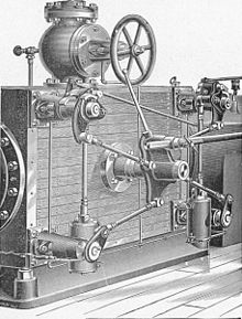
Porter-Allen high speed steam engine[edit]

Porter-Allen high speed engine. Enlarge to see the Porter governor at left front of flywheel
The Porter-Allen engine, introduced in 1862, used an advanced valve gear mechanism developed for Porter by Allen, a mechanic of exceptional ability, and was at first generally known as the Allen engine. The high speed engine was a precision machine that was well balanced, achievements made possible by advancements in machine tools and manufacturing technology.[45]
The high speed engine ran at piston speeds from three to five times the speed of ordinary engines. It also had low speed variability. The high speed engine was widely used in sawmills to power circular saws. Later it was used for electrical generation.
The engine had several advantages. It could, in some cases, be directly coupled. If gears or belts and drums were used, they could be much smaller sizes. The engine itself was also small for the amount of power it developed.[45]
Porter greatly improved the fly-ball governor by reducing the rotating weight and adding a weight around the shaft. This significantly improved speed control. Porter’s governor became the leading type by 1880.[citation needed]
The efficiency of the Porter-Allen engine was good, but not equal to the Corliss engine.[8]
Uniflow (or unaflow) engine[edit]
The uniflow engine was the most efficient type of high-pressure engine. It was invented in 1911 and was used in ships, but was displaced by steam turbines and later marine diesel engines.[45][46][47][12]
References[edit]
- ^ «turbine.» Encyclopædia Britannica. 2007. Encyclopædia Britannica Online. 18 July
- ^ Wiser, Wendell H. (2000). Energy resources: occurrence, production, conversion, use. Birkhäuser. p. 190. ISBN 978-0-387-98744-6.
- ^ Heron Alexandrinus (Hero of Alexandria) (c. 62 CE): Spiritalia seu Pneumatica. Reprinted 1998 by K G Saur GmbH, Munich. ISBN 3-519-01413-0.
- ^ a b c Dayton, Fred Erving (1925). «Two Thousand Years of Steam». Steamboat Days. Frederick A. Stokes company. p. 1.
- ^ Hero of Alexandria (1851). «Temple Doors opened by Fire on an Altar». Pneumatics of Hero of Alexandria. Bennet Woodcroft (trans.). London: Taylor Walton and Maberly (online edition from University of Rochester, Rochester, NY). Archived from the original on 2008-05-09. Retrieved 2008-04-23.
- ^ «Thurston, Robert (1878), «A history of the growth of the steam engine»«. History.rochester.edu. 1996-12-16. Archived from the original on 1997-06-29. Retrieved 2012-01-26.
- ^ Thurston, Robert Henry (1996). A History of the Growth of the Steam-Engine (reprint ed.). Elibron. p. 12. ISBN 1-4021-6205-7.
- ^ a b Taqi al-Din and the First Steam Turbine, 1551 A.D. Archived 2008-02-18 at the Wayback Machine, web page, accessed on line October 23, 2009; this web page refers to Ahmad Y Hassan (1976), Taqi al-Din and Arabic Mechanical Engineering, pp. 34-5, Institute for the History of Arabic Science, University of Aleppo.
- ^ «University of Rochester, NY, The growth of the steam engine online history resource, chapter one». History.rochester.edu. Archived from the original on 2012-02-04. Retrieved 2012-01-26.
- ^ Robert Henry Thurston, A history of the growth of the steam-engine, D. Appleton and company, 1903, Google Print, p.15-16 (public domain)
- ^ Garcia, Nicolas (2007). Mas alla de la Leyenda Negra. Valencia: Universidad de Valencia. pp. 443–454. ISBN 9788437067919.
- ^ a b McNeil, Ian (1990). An Encyclopedia of the History of Technology. London: Routledge. ISBN 0-415-14792-1.
- ^ a b c d e f g h Johnson, Steven (2008). The Invention of Air: A story of Science, Faith, Revolution and the Birth of America. New York: Riverhood Books. ISBN 978-1-59448-852-8.
- ^ Tredgold, pg. 3
- ^ Thurston, Robert Henry (1883). A History of the Growth of the Steam-Engine. London: Keegan Paul and Trench (reprinted Adamant 2001). pp. 21–22. ISBN 1-4021-6205-7.
- ^ a b Tredgold, pg. 6
- ^ a b
Landes, David. S. (1969). The Unbound Prometheus: Technological Change and Industrial Development in Western Europe from 1750 to the Present. Cambridge, New York: Press Syndicate of the University of Cambridge. ISBN 0-521-09418-6. - ^ a b L. T. C. Rolt and J. S. Allen, The Steam Engine of Thomas Newcomen (Landmark Publishing, Ashbourne 1997).
- ^ P. W. King. «Black Country Mining before the Industrial Revolution». Mining History: The Bulletin of the Peak District Mines History Society. 16 (6): 42–3.
- ^
Jenkins, Rhys (1936). Links in the History of Engineering and Technology from Tudor Times. Cambridge (1st), Books for Libraries Press (2nd): The Newcomen Society at the Cambridge University Press. ISBN 0-8369-2167-4The Colected Papers of Rhys Jenkins, Former Senior Examiner in the British Patent Office{{cite book}}: CS1 maint: location (link) CS1 maint: postscript (link) - ^ «Phil. Trans. 1751-1752 47, 436-438, published 1 January 1751». Philosophical Transactions of the Royal Society of London. 47: 436–438. 31 December 1752. doi:10.1098/rstl.1751.0073. S2CID 186208904.
- ^ Hulse David K (1999): «The early development of the steam engine»; TEE Publishing, Leamington Spa, UK, ISBN, 85761 107 1
- ^ «Paxton Engineering Division Report (2 of 3)». Content.cdlib.org. 2009-10-20. Retrieved 2012-01-26.
- ^ Tredgold, pg. 21-24
- ^ «Energy Hall | See ‘Old Bess’ at work». Science Museum. Archived from the original on 2012-02-05. Retrieved 2012-01-26.
- ^ a b c Roe, Joseph Wickham (1916), English and American Tool Builders, New Haven, Connecticut: Yale University Press, LCCN 16011753. Reprinted by McGraw-Hill, New York and London, 1926 (LCCN 27-24075); and by Lindsay Publications, Inc., Bradley, Illinois, (ISBN 978-0-917914-73-7).
- ^ Ogg, David. (1965), Europe of the Ancien Regime: 1715-1783 Fontana History of Europe, (pp. 117 & 283)
- ^ Tyler, David (2004): Oxford Dictionary of National Biography. Oxford University Press.
- ^ Ayres, Robert (1989). «Technological Transformations and Long Waves» (PDF): 13. Archived from the original (PDF) on 2012-03-01. Retrieved 2015-12-08.
- ^
Rosen, William (2012). The Most Powerful Idea in the World: A Story of Steam, Industry and Invention. University Of Chicago Press. p. 185. ISBN 978-0226726342. - ^ «The «Lap engine» in the Science Museum Group collection». collection.sciencemuseumgroup.org.uk. Retrieved 2020-05-11.
- ^ Hulse, David K., The development of rotary motion by steam power (TEE Publishing Ltd., Leamington, UK., 2001) ISBN 1-85761-119-5
- ^ Thomson, Ross (2009). Structures of Change in the Mechanical Age: Technological Invention in the United States 1790-1865. Baltimore, MD: The Johns Hopkins University Press. p. 47. ISBN 978-0-8018-9141-0.
- ^ Bennett, S. (1979). A History of Control Engineering 1800-1930. London: Peter Peregrinus Ltd. p. 2. ISBN 0-86341-047-2.
- ^ https://archive.org/stream/cu31924004249532#page/n45/mode/2up p.21
- ^ «The Steam Engine a brief history of the reciprocating engine, R.J.Law, Science Museum, Her Majesty’s Stationery Office London, ISBN 0 11 290016 X, p.12
- ^ «Member Login — Graces Guide» (PDF).
- ^ Meyer, David R (2006). Networked machinists: high-technology industries in Antebellum America. Johns Hopkins studies in the history of technology. Baltimore: Johns Hopkins University Press. p. 44. ISBN 978-0-8018-8471-9. OCLC 65340979.
- ^ «Engineering Timelines — Richard Trevithick — High pressure steam».
- ^ Young, Robert: «Timothy Hackworth and the Locomotive»; the Book guild Ltd, Lewes, U.K. (2000) (reprint of 1923 ed.) pp.18-21
- ^ Nuvolari, Alessandro; Verspagen, Bart (2007). «Lean’s Engine Reporter and the Cornish Engine». Transactions of the Newcomen Society. 77 (2): 167–190. doi:10.1179/175035207X204806. S2CID 56298553.
- ^ Nuvolari, Alessandro; Verspagen, Bart (2009). «Technical choice, innovation and British steam engineering, 1800-1850». Economic History Review. 63 (3): 685–710. doi:10.1111/j.1468-0289.2009.00472.x. S2CID 154050461.
- ^ Thomson, Ross (2009). Structures of Change in the Mechanical Age: Technological Invention in the United States 1790-1865. Baltimore, MD: The Johns Hopkins University Press. pp. 83–85. ISBN 978-0-8018-9141-0.
- ^ Thomson, p. 83-85.
- ^ a b c d Hunter, Louis C. (1985). A History of Industrial Power in the United States, 1730-1930, Vol. 2: Steam Power. Charlottesville: University Press of Virginia.
- ^ McNeil, Ian (1990). An Encyclopedia of the History of Technology. London: Routledge. ISBN 0415147921.
- ^ Marc Levinson (2006). The Box: How the Shipping Container Made the World Smaller and the World Economy Bigger. Princeton Univ. Press. ISBN 0-691-12324-1.Discusses engine types in the container shipping era but does not even mention uniflo.
Bibliography[edit]
- Gurr, Duncan; Hunt, Julian (1998). The Cotton Mills of Oldham. Oldham Education & Leisure. ISBN 0-902809-46-6. Archived from the original on 2011-07-18. Retrieved 2009-02-04.
- Roberts, A S (1921). «Arthur Robert’s Engine List». Arthur Roberts Black Book. One guy from Barlick-Book Transcription. Archived from the original on 2011-07-23. Retrieved 2009-01-11.
- Curtis, H P (1921). «Glossary of Textile Terms». Arthur Roberts Black Book. Manchester: Marsden & Company, Ltd. 1921. Archived from the original on 2011-10-06. Retrieved 2009-01-11.
- Nasmith, Joseph (1894). Recent Cotton Mill Construction and Engineering. John Heywood, Deansgate, Manchester, reprinted Elibron Classics. ISBN 1-4021-4558-6. Retrieved 2009-01-11.
- Hills, Richard Leslie (1993). Power from Steam: A History of the Stationary Steam Engine. Cambridge University Press. p. 244. ISBN 0-521-45834-X. Retrieved 10 January 2009.
- Taylor, «J.¨ (1827). «Thomas Tredgold». The Steam Engine. see Thomas Tredgold
Further reading[edit]
- Stuart, Robert, A Descriptive History of the Steam Engine, London: J. Knight and H. Lacey, 1824.
- Gascoigne, Bamber (2001). «History of Steam». HistoryWorld. Archived from the original on 8 January 2019. Retrieved 16 November 2009.
This article is about the history of the reciprocating-type steam engine. For the parallel development of turbine-type engines, see Steam turbine.
The 1698 Savery Steam Pump — the first commercially successful steam powered device, built by Thomas Savery
The first recorded rudimentary steam engine was the aeolipile mentioned by Vitruvius between 30 and 15 BC and, described by Heron of Alexandria in 1st-century Roman Egypt.[1] Several steam-powered devices were later experimented with or proposed, such as Taqi al-Din’s steam jack, a steam turbine in 16th-century Ottoman Egypt, and Thomas Savery’s steam pump in 17th-century England. In 1712, Thomas Newcomen’s atmospheric engine became the first commercially successful engine using the principle of the piston and cylinder, which was the fundamental type of steam engine used until the early 20th century. The steam engine was used to pump water out of coal mines.
During the Industrial Revolution, steam engines started to replace water and wind power, and eventually became the dominant source of power in the late 19th century and remaining so into the early decades of the 20th century, when the more efficient steam turbine and the internal combustion engine resulted in the rapid replacement of the steam engines. The steam turbine has become the most common method by which electrical power generators are driven.[2] Investigations are being made into the practicalities of reviving the reciprocating steam engine as the basis for the new wave of advanced steam technology.
Precursors[edit]
Early uses of steam power[edit]
The earliest known rudimentary steam engine and reaction steam turbine, the aeolipile, is described by a mathematician and engineer named Heron of Alexandria in 1st century Roman Egypt, as recorded in his manuscript Spiritalia seu Pneumatica.[3][4] The same device was also mentioned by Vitruvius in De Architectura about 100 years earlier. Steam ejected tangentially from nozzles caused a pivoted ball to rotate. Its thermal efficiency was low. This suggests that the conversion of steam pressure into mechanical movement was known in Roman Egypt in the 1st century. Heron also devised a machine that used air heated in an altar fire to displace a quantity of water from a closed vessel. The weight of the water was made to pull a hidden rope to operate temple doors.[4][5] Some historians have conflated the two inventions to assert, incorrectly, that the aeolipile was capable of useful work.[citation needed]
According to William of Malmesbury, in 1125, Reims was home to a church that had an organ powered by air escaping from compression «by heated water», apparently designed and constructed by professor Gerbertus.[4][6]
Among the papers of Leonardo da Vinci dating to the late 15th century is the design for a steam-powered cannon called the Architonnerre, which works by the sudden influx of hot water into a sealed, red-hot cannon.[7]
A rudimentary impact steam turbine was described in 1551 by Taqi al-Din, a philosopher, astronomer and engineer in 16th century Ottoman Egypt, who described a method for rotating a spit by means of a jet of steam playing on rotary vanes around the periphery of a wheel. A similar device for rotating a spit was also later described by John Wilkins in 1648.[8] These devices were then called «mills» but are now known as steam jacks. Another similar rudimentary steam turbine is shown by Giovanni Branca, an Italian engineer, in 1629 for turning a cylindrical escapement device that alternately lifted and let fall a pair of pestles working in mortars.[9] The steam flow of these early steam turbines, however, was not concentrated and most of its energy was dissipated in all directions. This would have led to a great waste of energy and so they were never seriously considered for industrial use.
In 1605, French mathematician Florence Rivault in his treatise on artillery wrote on his discovery that water, if confined in a bombshell and heated, would explode the shells.[10]
In 1606, the Spaniard Jerónimo de Ayanz y Beaumont demonstrated and was granted a patent for a steam-powered water pump. The pump was successfully used to drain the inundated mines of Guadalcanal, Spain.[11]
Development of the commercial steam engine[edit]
«The discoveries that, when brought together by Thomas Newcomen in 1712, resulted in the steam engine were:»[12]
- The concept of a vacuum (i.e. a reduction in pressure below ambient)
- The concept of pressure
- Techniques for creating a vacuum
- A means of generating steam
- The piston and cylinder
In 1643, Evangelista Torricelli conducted experiments on suction lift water pumps to test their limits, which was about 32 feet. (Atmospheric pressure is 32.9 feet or 10.03 meters. Vapor pressure of water lowers theoretical lift height.) He devised an experiment using a tube filled with mercury and inverted in a bowl of mercury (a barometer) and observed an empty space above the column of mercury, which he theorized contained nothing, that is, a vacuum.[13]
Influenced by Torricelli, Otto von Guericke invented a vacuum pump by modifying an air pump used for pressurizing an air gun. Guericke put on a demonstration in 1654 in Magdeburg, Germany, where he was mayor. Two copper hemispheres were fitted together and air was pumped out. Weights strapped to the hemispheres could not pull them apart until the air valve was opened. The experiment was repeated in 1656 using two teams of 8 horses each, which could not separate the Magdeburg hemispheres.[13]
Gaspar Schott was the first to describe the hemisphere experiment in his Mechanica Hydraulico-Pneumatica (1657).[13]
After reading Schott’s book, Robert Boyle built an improved vacuum pump and conducted related experiments.[13]
Denis Papin became interested in using a vacuum to generate motive power while working with Christiaan Huygens and Gottfried Leibniz in Paris in 1663. Papin worked for Robert Boyle from 1676 to 1679, publishing an account of his work in Continuation of New Experiments (1680) and gave a presentation to Royal Society in 1689. From 1690 on Papin began experimenting with a piston to produce power with steam, building model steam engines. He experimented with atmospheric and pressure steam engines, publishing his results in 1707.[13]
In 1663, Edward Somerset, 2nd Marquess of Worcester published a book of 100 inventions which described a method for raising water between floors employing a similar principle to that of a coffee percolator. His system was the first to separate the boiler (a heated cannon barrel) from the pumping action. Water was admitted into a reinforced barrel from a cistern, and then a valve was opened to admit steam from a separate boiler. The pressure built over the top of the water, driving it up a pipe.[14] He installed his steam-powered device on the wall of the Great Tower at Raglan Castle to supply water through the tower. The grooves in the wall where the engine was installed were still to be seen in the 19th century. However, no one was prepared to risk money for such a revolutionary concept, and without backers the machine remained undeveloped.[13][15]
Samuel Morland, a mathematician and inventor who worked on pumps, left notes at the Vauxhall Ordinance Office on a steam pump design that Thomas Savery read. In 1698 Savery built a steam pump called «The Miner’s Friend.» It employed both vacuum and pressure. These were used for low horsepower service for a number of years.[13]
Thomas Newcomen was a merchant who dealt in cast iron goods. Newcomen’s engine was based on the piston and cylinder design proposed by Papin. In Newcomen’s engine steam was condensed by water sprayed inside the cylinder, causing atmospheric pressure to move the piston. Newcomen’s first engine installed for pumping in a mine in 1712 at Dudley Castle in Staffordshire.[13]
Cylinders[edit]
Denis Papin’s design for a piston-and-cylinder engine, 1680.
Denis Papin (22 August 1647 – c. 1712) was a French physicist, mathematician and inventor, best known for his pioneering invention of the steam digester, the forerunner of the pressure cooker. In the mid-1670s Papin collaborated with the Dutch physicist Christiaan Huygens on an engine which drove out the air from a cylinder by exploding gunpowder inside it. Realising the incompleteness of the vacuum produced by this means and on moving to England in 1680, Papin devised a version of the same cylinder that obtained a more complete vacuum from boiling water and then allowing the steam to condense; in this way he was able to raise weights by attaching the end of the piston to a rope passing over a pulley. As a demonstration model, the system worked, but in order to repeat the process, the whole apparatus had to be dismantled and reassembled. Papin quickly saw that to make an automatic cycle the steam would have to be generated separately in a boiler; however, he did not take the project further. Papin also designed a paddle boat driven by a jet playing on a mill-wheel in a combination of Taqi al Din and Savery’s conceptions and he is also credited with a number of significant devices such as the safety valve. Papin’s years of research into the problems of harnessing steam was to play a key part in the development of the first successful industrial engines that soon followed his death.
Savery steam pump[edit]
The first steam engine to be applied industrially was the «fire-engine» or «Miner’s Friend», designed by Thomas Savery in 1698. This was a pistonless steam pump, similar to the one developed by Worcester. Savery made two key contributions that greatly improved the practicality of the design. First, in order to allow the water supply to be placed below the engine, he used condensed steam to produce a partial vacuum in the pumping reservoir (the barrel in Worcester’s example), and using that to pull the water upward. Secondly, in order to rapidly cool the steam to produce the vacuum, he ran cold water over the reservoir.
Operation required several valves; at the start of a cycle, when the reservoir was empty, a valve would be opened to admit steam. This valve would be closed to seal the reservoir, and the cooling water valve would be opened to condense the steam and create a partial vacuum. A supply valve would then be opened, pulling water upward into the reservoir; the typical engine could pull water up to 20 feet.[16] This was then closed, and the steam valve reopened, building pressure over the water and pumping it upward, as in the Worcester design. This cycle essentially doubled the distance that water could be pumped for any given pressure of steam, and production examples raised water about 40 feet.[16]
Savery’s engine solved a problem that had only recently become a serious one; raising water out of the mines in southern England as they reached greater depths. Savery’s engine was somewhat less efficient than Newcomen’s, but this was compensated for by the fact that the separate pump used by the Newcomen engine was inefficient, giving the two engines roughly the same efficiency of 6 million foot pounds per bushel of coal (less than 1%).[17] Nor was the Savery engine very safe because part of its cycle required steam under pressure supplied by a boiler, and given the technology of the period the pressure vessel could not be made strong enough and so was prone to explosion.[18] The explosion of one of his pumps at Broad Waters (near Wednesbury), about 1705, probably marks the end of attempts to exploit his invention.[19]
The Savery engine was less expensive than Newcomen’s and was produced in smaller sizes.[20] Some builders were manufacturing improved versions of the Savery engine until late in the 18th century.[17] Bento de Moura Portugal, FRS, introduced an ingenious improvement of Savery’s construction «to render it capable of working itself», as described by John Smeaton in the Philosophical Transactions published in 1751.[21]
Atmospheric condensing engines[edit]
Newcomen «atmospheric» engine[edit]
Engraving of Newcomen engine. This appears to be copied from a drawing in Desaguliers’ 1744 work: «A course of experimental philosophy», itself believed to have been a reversed copy of Henry Beighton’s engraving dated 1717, that may represent what is probably the second Newcomen engine erected around 1714 at Griff colliery, Warwickshire.[22]
It was Thomas Newcomen with his «atmospheric-engine» of 1712 who can be said to have brought together most of the essential elements established by Papin in order to develop the first practical steam engine for which there could be a commercial demand. This took the shape of a reciprocating beam engine installed at surface level driving a succession of pumps at one end of the beam. The engine, attached by chains from other end of the beam, worked on the atmospheric, or vacuum principle.[23]
Newcomen’s design used some elements of earlier concepts. Like the Savery design, Newcomen’s engine used steam, cooled with water, to create a vacuum. Unlike Savery’s pump, however, Newcomen used the vacuum to pull on a piston instead of pulling on water directly. The upper end of the cylinder was open to the atmospheric pressure, and when the vacuum formed, the atmospheric pressure above the piston pushed it down into the cylinder. The piston was lubricated and sealed by a trickle of water from the same cistern that supplied the cooling water. Further, to improve the cooling effect, he sprayed water directly into the cylinder.
The piston was attached by a chain to a large pivoted beam. When the piston pulled the beam, the other side of the beam was pulled upward. This end was attached to a rod that pulled on a series of conventional pump handles in the mine. At the end of this power stroke, the steam valve was reopened, and the weight of the pump rods pulled the beam down, lifting the piston and drawing steam into the cylinder again.
Using the piston and beam allowed the Newcomen engine to power pumps at different levels throughout the mine, as well as eliminating the need for any high-pressure steam. The entire system was isolated to a single building on the surface. Although inefficient and extremely heavy on coal (compared to later engines), these engines raised far greater volumes of water and from greater depths than had previously been possible.[18] Over 100 Newcomen engines were installed around England by 1735, and it is estimated that as many as 2,000 were in operation by 1800 (including Watt versions).
John Smeaton made numerous improvements to the Newcomen engine, notably the seals, and by improving these was able to almost triple their efficiency. He also preferred to use wheels instead of beams for transferring power from the cylinder, which made his engines more compact. Smeaton was the first to develop a rigorous theory of steam engine design of operation. He worked backward from the intended role to calculate the amount of power that would be needed for the task, the size and speed of a cylinder that would provide it, the size of boiler needed to feed it, and the amount of fuel it would consume. These were developed empirically after studying dozens of Newcomen engines in Cornwall and Newcastle, and building an experimental engine of his own at his home in Austhorpe in 1770. By the time the Watt engine was introduced only a few years later, Smeaton had built dozens of ever-larger engines into the 100 hp range.[24]
Watt’s separate condenser[edit]
Early Watt pumping engine.
While working at the University of Glasgow as an instrument maker and repairman in 1759, James Watt was introduced to the power of steam by Professor John Robison. Fascinated, Watt took to reading everything he could on the subject, and independently developed the concept of latent heat, only recently published by Joseph Black at the same university. When Watt learned that the University owned a small working model of a Newcomen engine, he pressed to have it returned from London where it was being unsuccessfully repaired. Watt repaired the machine, but found it was barely functional even when fully repaired.
After working with the design, Watt concluded that 80% of the steam used by the engine was wasted. Instead of providing motive force, it was instead being used to heat the cylinder. In the Newcomen design, every power stroke was started with a spray of cold water, which not only condensed the steam, but also cooled the walls of the cylinder. This heat had to be replaced before the cylinder would accept steam again. In the Newcomen engine the heat was supplied only by the steam, so when the steam valve was opened again the vast majority condensed on the cold walls as soon as it was admitted to the cylinder. It took a considerable amount of time and steam before the cylinder warmed back up and the steam started to fill it up.
Watt solved the problem of the water spray by removing the cold water to a different cylinder, placed beside the power cylinder. Once the induction stroke was complete a valve was opened between the two, and any steam that entered the cylinder would condense inside this cold cylinder. This would create a vacuum that would pull more of the steam into the cylinder, and so on until the steam was mostly condensed. The valve was then closed, and operation of the main cylinder continued as it would on a conventional Newcomen engine. As the power cylinder remained at operational temperature throughout, the system was ready for another stroke as soon as the piston was pulled back to the top. Maintaining the temperature was a jacket around the cylinder where steam was admitted. Watt produced a working model in 1765.
Convinced that this was a great advance, Watt entered into partnerships to provide venture capital while he worked on the design. Not content with this single improvement, Watt worked tirelessly on a series of other improvements to practically every part of the engine. Watt further improved the system by adding a small vacuum pump to pull the steam out of the cylinder into the condenser, further improving cycle times. A more radical change from the Newcomen design was closing off the top of the cylinder and introducing low-pressure steam above the piston. Now the power was not due to the difference of atmospheric pressure and the vacuum, but the pressure of the steam and the vacuum, a somewhat higher value. On the upward return stroke, the steam on top was transferred through a pipe to the underside of the piston ready to be condensed for the downward stroke. Sealing of the piston on a Newcomen engine had been achieved by maintaining a small quantity of water on its upper side. This was no longer possible in Watt’s engine due to the presence of the steam. Watt spent considerable effort to find a seal that worked, eventually obtained by using a mixture of tallow and oil. The piston rod also passed through a gland on the top cylinder cover sealed in a similar way.[25]
The piston sealing problem was due to having no way to produce a sufficiently round cylinder. Watt tried having cylinders bored from cast iron, but they were too out of round. Watt was forced to use a hammered iron cylinder.[26] The following quotation is from Roe (1916):
«When [John] Smeaton first saw the engine he reported to the Society of Engineers that ‘neither the tools nor the workmen existed who could manufacture such a complex machine with sufficient precision’ «[26]
Watt finally considered the design good enough to release in 1774, and the Watt engine was released to the market. As portions of the design could be easily fitted to existing Newcomen engines, there was no need to build an entirely new engine at the mines. Instead, Watt and his business partner Matthew Boulton licensed the improvements to engine operators, charging them a portion of the money they would save in reduced fuel costs. The design was wildly successful, and the Boulton and Watt company was formed to license the design and help new manufacturers build the engines. The two would later open the Soho Foundry to produce engines of their own.
In 1774, John Wilkinson invented a boring machine with the shaft holding the boring tool supported on both ends, extending through the cylinder, unlike the then used cantilevered borers. With this machine he was able to successfully bore the cylinder for Boulton and Watt’s first commercial engine in 1776.[26]
Watt never ceased improving his designs. This further improved the operating cycle speed, introduced governors, automatic valves, double-acting pistons, a variety of rotary power takeoffs and many other improvements. Watt’s technology enabled the widespread commercial use of stationary steam engines.[27]
Humphrey Gainsborough produced a model condensing steam engine in the 1760s, which he showed to Richard Lovell Edgeworth, a member of the Lunar Society. Gainsborough believed that Watt had used his ideas for the invention;[28] however, James Watt was not a member of the Lunar Society at this period and his many accounts explaining the succession of thought processes leading to the final design would tend to belie this story.
Power was still limited by the low pressure, the displacement of the cylinder, combustion and evaporation rates and condenser capacity. Maximum theoretical efficiency was limited by the relatively low temperature differential on either side of the piston; this meant that for a Watt engine to provide a usable amount of power, the first production engines had to be very large, and were thus expensive to build and install.
Watt double-acting and rotative engines[edit]
Watt developed a double-acting engine in which steam drove the piston in both directions, thereby increasing the engine speed and efficiency. The double-acting principle also significantly increased the output of a given physical sized engine.[29][30]
Boulton & Watt developed the reciprocating engine into the rotative type. Unlike the Newcomen engine, the Watt engine could operate smoothly enough to be connected to a drive shaft – via sun and planet gears – to provide rotary power along with double-acting condensing cylinders. The earliest example was built as a demonstrator and was installed in Boulton’s factory to work machines for lapping (polishing) buttons or similar. For this reason it was always known as the Lap Engine.[31][32] In early steam engines the piston is usually connected by a rod to a balanced beam, rather than directly to a flywheel, and these engines are therefore known as beam engines.
Early steam engines did not provide constant enough speed for critical operations such as cotton spinning. To control speed the engine was used to pump water for a water wheel, which powered the machinery.[33][34]
High-pressure engines[edit]
As the 18th century advanced, the call was for higher pressures; this was strongly resisted by Watt who used the monopoly his patent gave him to prevent others from building high-pressure engines and using them in vehicles. He mistrusted the boiler technology of the day, the way they were constructed and the strength of the materials used.
The important advantages of high-pressure engines were:
- They could be made much smaller than previously for a given power output. There was thus the potential for steam engines to be developed that were small and powerful enough to propel themselves and other objects. As a result, steam power for transportation now became a practicality in the form of ships and land vehicles, which revolutionised cargo businesses, travel, military strategy, and essentially every aspect of society.
- Because of their smaller size, they were much less expensive.
- They did not require the significant quantities of condenser cooling water needed by atmospheric engines.
- They could be designed to run at higher speeds, making them more suitable for powering machinery.
The disadvantages were:
- In the low-pressure range they were less efficient than condensing engines, especially if steam was not used expansively.
- They were more susceptible to boiler explosions.
The main difference between how high-pressure and low-pressure steam engines work is the source of the force that moves the piston. In the engines of Newcomen and Watt, it is the condensation of the steam that creates most of the pressure difference, causing atmospheric pressure (Newcomen) and low-pressure steam, seldom more than 7 psi boiler pressure,[35] plus condenser vacuum[36] (Watt), to move the piston. In a high-pressure engine, most of the pressure difference is provided by the high-pressure steam from the boiler; the low-pressure side of the piston may be at atmospheric pressure or connected to the condenser pressure. Newcomen’s indicator diagram, almost all below the atmospheric line, would see a revival nearly 200 years later with the low pressure cylinder of triple expansion engines contributing about 20% of the engine power, again almost completely below the atmospheric line.[37]
The first known advocate of «strong steam» was Jacob Leupold in his scheme for an engine that appeared in encyclopaedic works from c. 1725. Various projects for steam propelled boats and vehicles also appeared throughout the century, one of the most promising being the construction of Nicolas-Joseph Cugnot, who demonstrated his «fardier» (steam wagon) in 1769. Whilst the working pressure used for this vehicle is unknown, the small size of the boiler gave insufficient steam production rate to allow the fardier to advance more than a few hundred metres at a time before having to stop to raise steam. Other projects and models were proposed, but as with William Murdoch’s model of 1784, many were blocked by Boulton and Watt.
This did not apply in the US, and in 1788 a steamboat built by John Fitch operated in regular commercial service along the Delaware River between Philadelphia, Pennsylvania, and Burlington, New Jersey, carrying as many as 30 passengers. This boat could typically make 7 to 8 miles per hour, and traveled more than 2,000 miles (3,200 km) during its short length of service. The Fitch steamboat was not a commercial success, as this route was adequately covered by relatively good wagon roads. In 1802, William Symington built a practical steamboat, and in 1807, Robert Fulton used a Watt steam engine to power the first commercially successful steamboat.[citation needed]
Oliver Evans in his turn was in favour of «strong steam» which he applied to boat engines and to stationary uses. He was a pioneer of cylindrical boilers; however, Evans’ boilers did suffer several serious boiler explosions, which tended to lend weight to Watt’s qualms. He founded the Pittsburgh Steam Engine Company in 1811 in Pittsburgh, Pennsylvania.[38]
The company introduced high-pressure steam engines to the riverboat trade in the Mississippi watershed.
The first high-pressure steam engine was invented in 1800 by Richard Trevithick.[39]
The importance of raising steam under pressure (from a thermodynamic standpoint) is that it attains a higher temperature. Thus, any engine using high-pressure steam operates at a higher temperature and pressure differential than is possible with a low-pressure vacuum engine. The high-pressure engine thus became the basis for most further development of reciprocating steam technology. Even so, around the year 1800, «high pressure» amounted to what today would be considered very low pressure, i.e. 40-50 psi (276-345 kPa), the point being that the high-pressure engine in question was non-condensing, driven solely by the expansive power of the steam, and once that steam had performed work it was usually exhausted at higher-than-atmospheric pressure. The blast of the exhausting steam into the chimney could be exploited to create induced draught through the fire grate and thus increase the rate of burning, hence creating more heat in a smaller furnace, at the expense of creating back pressure on the exhaust side of the piston.
On 21 February 1804, at the Penydarren ironworks at Merthyr Tydfil in South Wales, the first self-propelled railway steam engine or steam locomotive, built by Richard Trevithick, was demonstrated.[40]
Cornish engine and compounding[edit]
Trevithick pumping engine (Cornish system).
Around 1811, Richard Trevithick was required to update a Watt pumping engine in order to adapt it to one of his new large cylindrical Cornish boilers. When Trevithick left for South America in 1816, his improvements were continued by William Sims. In a parallel, Arthur Woolf developed a compound engine with two cylinders, so that steam expanded in a high-pressure cylinder before being released into a low-pressure one. Efficiency was further improved by Samuel Groase, who insulated the boiler, engine, and pipes.[41]
Steam pressure above the piston was increased eventually reaching 40 psi (0.28 MPa) or even 50 psi (0.34 MPa) and now provided much of the power for the downward stroke; at the same time condensing was improved. This considerably raised efficiency and further pumping engines on the Cornish system (often known as Cornish engines) continued to be built new throughout the 19th century. Older Watt engines were updated to conform.
The take-up of these Cornish improvements was slow in textile manufacturing areas where coal was cheap, due to the higher capital cost of the engines and the greater wear that they suffered. The change only began in the 1830s, usually by compounding through adding another (high-pressure) cylinder.[42]
Another limitation of early steam engines was speed variability, which made them unsuitable for many textile applications, especially spinning. In order to obtain steady speeds, early steam powered textile mills used the steam engine to pump water to a water wheel, which drove the machinery.[43]
Many of these engines were supplied worldwide and gave reliable and efficient service over a great many years with greatly reduced coal consumption. Some of them were very large and the type continued to be built right down to the 1890s.
Corliss engine[edit]
«Gordon’s improved Corliss valvegear», detailed view. The wrist-plate is the central plate from which rods radiate to each of the 4 valves.
The Corliss steam engine (patented 1849) was called the greatest improvement since James Watt.[44] The Corliss engine had greatly improved speed control and better efficiency, making it suitable to all sorts of industrial applications, including spinning.
Corliss used separate ports for steam supply and exhaust, which prevented the exhaust from cooling the passage used by the hot steam. Corliss also used partially rotating valves that provided quick action, helping to reduce pressure losses. The valves themselves were also a source of reduced friction, especially compared to the slide valve, which typically used 10% of an engine’s power.[45]
Corliss used automatic variable cut off. The valve gear controlled engine speed by using the governor to vary the timing of the cut off. This was partly responsible for the efficiency improvement in addition to the better speed control.
Porter-Allen high speed steam engine[edit]
Porter-Allen high speed engine. Enlarge to see the Porter governor at left front of flywheel
The Porter-Allen engine, introduced in 1862, used an advanced valve gear mechanism developed for Porter by Allen, a mechanic of exceptional ability, and was at first generally known as the Allen engine. The high speed engine was a precision machine that was well balanced, achievements made possible by advancements in machine tools and manufacturing technology.[45]
The high speed engine ran at piston speeds from three to five times the speed of ordinary engines. It also had low speed variability. The high speed engine was widely used in sawmills to power circular saws. Later it was used for electrical generation.
The engine had several advantages. It could, in some cases, be directly coupled. If gears or belts and drums were used, they could be much smaller sizes. The engine itself was also small for the amount of power it developed.[45]
Porter greatly improved the fly-ball governor by reducing the rotating weight and adding a weight around the shaft. This significantly improved speed control. Porter’s governor became the leading type by 1880.[citation needed]
The efficiency of the Porter-Allen engine was good, but not equal to the Corliss engine.[8]
Uniflow (or unaflow) engine[edit]
The uniflow engine was the most efficient type of high-pressure engine. It was invented in 1911 and was used in ships, but was displaced by steam turbines and later marine diesel engines.[45][46][47][12]
References[edit]
- ^ «turbine.» Encyclopædia Britannica. 2007. Encyclopædia Britannica Online. 18 July
- ^ Wiser, Wendell H. (2000). Energy resources: occurrence, production, conversion, use. Birkhäuser. p. 190. ISBN 978-0-387-98744-6.
- ^ Heron Alexandrinus (Hero of Alexandria) (c. 62 CE): Spiritalia seu Pneumatica. Reprinted 1998 by K G Saur GmbH, Munich. ISBN 3-519-01413-0.
- ^ a b c Dayton, Fred Erving (1925). «Two Thousand Years of Steam». Steamboat Days. Frederick A. Stokes company. p. 1.
- ^ Hero of Alexandria (1851). «Temple Doors opened by Fire on an Altar». Pneumatics of Hero of Alexandria. Bennet Woodcroft (trans.). London: Taylor Walton and Maberly (online edition from University of Rochester, Rochester, NY). Archived from the original on 2008-05-09. Retrieved 2008-04-23.
- ^ «Thurston, Robert (1878), «A history of the growth of the steam engine»«. History.rochester.edu. 1996-12-16. Archived from the original on 1997-06-29. Retrieved 2012-01-26.
- ^ Thurston, Robert Henry (1996). A History of the Growth of the Steam-Engine (reprint ed.). Elibron. p. 12. ISBN 1-4021-6205-7.
- ^ a b Taqi al-Din and the First Steam Turbine, 1551 A.D. Archived 2008-02-18 at the Wayback Machine, web page, accessed on line October 23, 2009; this web page refers to Ahmad Y Hassan (1976), Taqi al-Din and Arabic Mechanical Engineering, pp. 34-5, Institute for the History of Arabic Science, University of Aleppo.
- ^ «University of Rochester, NY, The growth of the steam engine online history resource, chapter one». History.rochester.edu. Archived from the original on 2012-02-04. Retrieved 2012-01-26.
- ^ Robert Henry Thurston, A history of the growth of the steam-engine, D. Appleton and company, 1903, Google Print, p.15-16 (public domain)
- ^ Garcia, Nicolas (2007). Mas alla de la Leyenda Negra. Valencia: Universidad de Valencia. pp. 443–454. ISBN 9788437067919.
- ^ a b McNeil, Ian (1990). An Encyclopedia of the History of Technology. London: Routledge. ISBN 0-415-14792-1.
- ^ a b c d e f g h Johnson, Steven (2008). The Invention of Air: A story of Science, Faith, Revolution and the Birth of America. New York: Riverhood Books. ISBN 978-1-59448-852-8.
- ^ Tredgold, pg. 3
- ^ Thurston, Robert Henry (1883). A History of the Growth of the Steam-Engine. London: Keegan Paul and Trench (reprinted Adamant 2001). pp. 21–22. ISBN 1-4021-6205-7.
- ^ a b Tredgold, pg. 6
- ^ a b
Landes, David. S. (1969). The Unbound Prometheus: Technological Change and Industrial Development in Western Europe from 1750 to the Present. Cambridge, New York: Press Syndicate of the University of Cambridge. ISBN 0-521-09418-6. - ^ a b L. T. C. Rolt and J. S. Allen, The Steam Engine of Thomas Newcomen (Landmark Publishing, Ashbourne 1997).
- ^ P. W. King. «Black Country Mining before the Industrial Revolution». Mining History: The Bulletin of the Peak District Mines History Society. 16 (6): 42–3.
- ^
Jenkins, Rhys (1936). Links in the History of Engineering and Technology from Tudor Times. Cambridge (1st), Books for Libraries Press (2nd): The Newcomen Society at the Cambridge University Press. ISBN 0-8369-2167-4The Colected Papers of Rhys Jenkins, Former Senior Examiner in the British Patent Office{{cite book}}: CS1 maint: location (link) CS1 maint: postscript (link) - ^ «Phil. Trans. 1751-1752 47, 436-438, published 1 January 1751». Philosophical Transactions of the Royal Society of London. 47: 436–438. 31 December 1752. doi:10.1098/rstl.1751.0073. S2CID 186208904.
- ^ Hulse David K (1999): «The early development of the steam engine»; TEE Publishing, Leamington Spa, UK, ISBN, 85761 107 1
- ^ «Paxton Engineering Division Report (2 of 3)». Content.cdlib.org. 2009-10-20. Retrieved 2012-01-26.
- ^ Tredgold, pg. 21-24
- ^ «Energy Hall | See ‘Old Bess’ at work». Science Museum. Archived from the original on 2012-02-05. Retrieved 2012-01-26.
- ^ a b c Roe, Joseph Wickham (1916), English and American Tool Builders, New Haven, Connecticut: Yale University Press, LCCN 16011753. Reprinted by McGraw-Hill, New York and London, 1926 (LCCN 27-24075); and by Lindsay Publications, Inc., Bradley, Illinois, (ISBN 978-0-917914-73-7).
- ^ Ogg, David. (1965), Europe of the Ancien Regime: 1715-1783 Fontana History of Europe, (pp. 117 & 283)
- ^ Tyler, David (2004): Oxford Dictionary of National Biography. Oxford University Press.
- ^ Ayres, Robert (1989). «Technological Transformations and Long Waves» (PDF): 13. Archived from the original (PDF) on 2012-03-01. Retrieved 2015-12-08.
- ^
Rosen, William (2012). The Most Powerful Idea in the World: A Story of Steam, Industry and Invention. University Of Chicago Press. p. 185. ISBN 978-0226726342. - ^ «The «Lap engine» in the Science Museum Group collection». collection.sciencemuseumgroup.org.uk. Retrieved 2020-05-11.
- ^ Hulse, David K., The development of rotary motion by steam power (TEE Publishing Ltd., Leamington, UK., 2001) ISBN 1-85761-119-5
- ^ Thomson, Ross (2009). Structures of Change in the Mechanical Age: Technological Invention in the United States 1790-1865. Baltimore, MD: The Johns Hopkins University Press. p. 47. ISBN 978-0-8018-9141-0.
- ^ Bennett, S. (1979). A History of Control Engineering 1800-1930. London: Peter Peregrinus Ltd. p. 2. ISBN 0-86341-047-2.
- ^ https://archive.org/stream/cu31924004249532#page/n45/mode/2up p.21
- ^ «The Steam Engine a brief history of the reciprocating engine, R.J.Law, Science Museum, Her Majesty’s Stationery Office London, ISBN 0 11 290016 X, p.12
- ^ «Member Login — Graces Guide» (PDF).
- ^ Meyer, David R (2006). Networked machinists: high-technology industries in Antebellum America. Johns Hopkins studies in the history of technology. Baltimore: Johns Hopkins University Press. p. 44. ISBN 978-0-8018-8471-9. OCLC 65340979.
- ^ «Engineering Timelines — Richard Trevithick — High pressure steam».
- ^ Young, Robert: «Timothy Hackworth and the Locomotive»; the Book guild Ltd, Lewes, U.K. (2000) (reprint of 1923 ed.) pp.18-21
- ^ Nuvolari, Alessandro; Verspagen, Bart (2007). «Lean’s Engine Reporter and the Cornish Engine». Transactions of the Newcomen Society. 77 (2): 167–190. doi:10.1179/175035207X204806. S2CID 56298553.
- ^ Nuvolari, Alessandro; Verspagen, Bart (2009). «Technical choice, innovation and British steam engineering, 1800-1850». Economic History Review. 63 (3): 685–710. doi:10.1111/j.1468-0289.2009.00472.x. S2CID 154050461.
- ^ Thomson, Ross (2009). Structures of Change in the Mechanical Age: Technological Invention in the United States 1790-1865. Baltimore, MD: The Johns Hopkins University Press. pp. 83–85. ISBN 978-0-8018-9141-0.
- ^ Thomson, p. 83-85.
- ^ a b c d Hunter, Louis C. (1985). A History of Industrial Power in the United States, 1730-1930, Vol. 2: Steam Power. Charlottesville: University Press of Virginia.
- ^ McNeil, Ian (1990). An Encyclopedia of the History of Technology. London: Routledge. ISBN 0415147921.
- ^ Marc Levinson (2006). The Box: How the Shipping Container Made the World Smaller and the World Economy Bigger. Princeton Univ. Press. ISBN 0-691-12324-1.Discusses engine types in the container shipping era but does not even mention uniflo.
Bibliography[edit]
- Gurr, Duncan; Hunt, Julian (1998). The Cotton Mills of Oldham. Oldham Education & Leisure. ISBN 0-902809-46-6. Archived from the original on 2011-07-18. Retrieved 2009-02-04.
- Roberts, A S (1921). «Arthur Robert’s Engine List». Arthur Roberts Black Book. One guy from Barlick-Book Transcription. Archived from the original on 2011-07-23. Retrieved 2009-01-11.
- Curtis, H P (1921). «Glossary of Textile Terms». Arthur Roberts Black Book. Manchester: Marsden & Company, Ltd. 1921. Archived from the original on 2011-10-06. Retrieved 2009-01-11.
- Nasmith, Joseph (1894). Recent Cotton Mill Construction and Engineering. John Heywood, Deansgate, Manchester, reprinted Elibron Classics. ISBN 1-4021-4558-6. Retrieved 2009-01-11.
- Hills, Richard Leslie (1993). Power from Steam: A History of the Stationary Steam Engine. Cambridge University Press. p. 244. ISBN 0-521-45834-X. Retrieved 10 January 2009.
- Taylor, «J.¨ (1827). «Thomas Tredgold». The Steam Engine. see Thomas Tredgold
Further reading[edit]
- Stuart, Robert, A Descriptive History of the Steam Engine, London: J. Knight and H. Lacey, 1824.
- Gascoigne, Bamber (2001). «History of Steam». HistoryWorld. Archived from the original on 8 January 2019. Retrieved 16 November 2009.
История паровых машин
- Статья опубликована 19.05.2014 05:36
- Последняя правка произведена 19.05.2014 05:58

Паровая машина
О истории развития парового двигателя, достаточно подробно описано в этой статье. Тут же — наиболее известные решения и изобретения времен 1672-1891 года.
Первые наработки.
Начнем с того, что еще в семнадцатом веке пар стали рассматривать как средство для привода, проводили с ним всяческие опыты, и лишь только в 1643 году Эванджелистом Торричелли было открыто силовое действие давления пара. Кристиан Гюйгенс через 47 лет спроектировал первую силовую машину, приводившуюся в действие взрывом пороха в цилиндре. Это был первый прототип двигателя внутреннего сгорания. На аналогичном принципе устроена водозаборная машина аббата Отфея. Вскоре Дени Папен решил заменить силу взрыва на менее мощную силу пара. В 1690 году им была построена первая паровая машина, известная также как паровой котел.
Она состояла из поршня, который с помощью кипящей воды перемещался в цилиндре вверх и за счет последующего охлаждения снова опускался – так создавалось усилие. Весь процесс происходил таким образом: под цилиндром, который выполнял одновременно и функцию кипятильного котла, размещали печь; при нахождении поршня в верхнем положении печь отодвигалась для облегчения охлаждения.

Автомобиль Куньо

Реактивный автомобиль Ньютона

Паровая машина Фербиста
Превью — увеличение по клику.
Позже два англичанина, Томас Ньюкомен и Коули – один кузнец, другой стекольщик, – усовершенствовали систему путем разделения кипятильного котла и цилиндра и добавления бака с холодной водой. Эта система функционировала с помощью клапанов или кранов – одного для пара и одного для воды, которые поочередно открывались и закрывались. Затем англичанин Бэйтон перестроил клапанное управление в подлинно тактовое.
Применение паровых машин на практике.
Машина Ньюкомена вскоре стала известна повсюду и, в частности, была усовершенствована, разработанной Джеймсом Уаттом в 1765 году системой двойного действия. Теперь паровая машина оказалась достаточно завершенной для использования в транспортных средствах, хотя из-за своих размеров лучше подходила для стационарных установок. Уатт предложил свои изобретения и в промышленности; он построил также машины для текстильных фабрик.
Первая паровая машина, используемая в качестве средства передвижения, был изобретена французом Николя Жозефом Куньо, инженером и военным стратегпм-любителем. В 1763 или 1765 году он создал автомобиль, который мог перевозить четырех пассажиров при средней скорости 3,5 и максимальной – 9,5 км/час. За первой попыткой последовала вторая – появился автомобиль для транспортировки орудий. Испытывался он, естественно, военными, но из-за невозможности продолжительной эксплуатации (непрерывный цикл работы новой машины не превышал 15 минут) изобретатель не получил поддержки властей и финансистов. Между тем в Англии совершенствовалась паровая машина. После нескольких безуспешных, базировавшихся на машине Уаттa попыток Мура, Вильяма Мердока и Вильяма Саймингтона, появилось рельсовое транспортное средство Ричарда Тревисика, созданное по заказу Уэльской угольной шахты. В мир пришел активный изобретатель: из подземных шахт он поднялся на землю и в 1802 году представил человечеству мощный легковой автомобиль, достигавший скорости 15 км/час на ровной местности и 6 км/час на подъеме.

Паровая Карета Гарни

Карета Хилла

Паровая карета
Превью — увеличение по клику.
Приводимые в движение паром транспортные средства все чаще использовались и в США: Натан Рид в 1790 году удивил жителей Филадельфии своей моделью парового автомобиля. Однако еще больше прославился его соотечественник Оливер Эванс, который спустя четырнадцать лет изобрел автомобиль-амфибию. После наполеоновских войн, во время которых «автомобильные эксперименты» не проводились, вновь началась работа над изобретением и усовершенствованием паровой машины. В 1821 году ее можно было считать совершенной и достаточно надежной. С тех пор каждый шаг вперед в сфере приводимых в движение паром транспортных средств определенно способствовал развитию будущих автомобилей.
В 1825 году сэр Голдсуорт Гарни на участке длиной 171 км от Лондона до Бата организовал первую пассажирскую линию. При этом он использовал запатентованную им карету, имевшую паровой двигатель. Это стало началом эпохи скоростных дорожных экипажей, которые, однако, исчезли в Англии, но получили широкое распространение в Италии и во Франции. Подобные транспортные средства достигли наивысшего развития с появлением в 1873 году «Реверанса» Амедэ Балле весом 4500 кг и «Манселя» – более компактного, весившего чуть более 2500 кг и достигавшего скорости 35 км/час. Оба были предвестниками той техники исполнения, которая стала характерной для первых «настоящих» автомобилей. Несмотря на большую скорость кпд паровой машины был очень маленький. Болле был тем, кто запатентовал первую хорошо действующую систему рулевого управления, он так удачно расположил управляющие и контрольные элементы, что мы и сегодня это видим на приборном щитке.

транспортное средство Болле-Марселя

Машина Бордино
Превью — увеличение по клику.
Несмотря на грандиозный прогресс в области создания двигателя внутреннего сгорания, сила пара все еще обеспечивала более равномерный и плавный ход машины и, следовательно, имела много сторонников. Как и Болле, который построил и другие легкие автомобили, например Rapide в 1881 году со скоростью движения 60 км/час, Nouvelle в 1873 году, которая имела переднюю ось с независимой подвеской колес, Леон Шевроле в период между 1887 и 1907 годами запустил несколько автомобилей с легким и компактным парогенератором, запатентованным им в 1889 году. Компания De Dion-Bouton, основанная в Париже в 1883 году, первые десять лет своего существования производила автомобили с паровым двигателями и добилась при этом значительного успеха – ее автомобили выиграли гонки Париж-Руан в 1894 году.

Машина Хенкока

Трехколесник Пекори
Превью — увеличение по клику.
Успехи компании Panhard et Levassor в использовании бензина привели, однако, к тому, что и De Dion перешел на двигатели внутреннего сгорания. Когда братья Болле стали управлять компанией своего отца, они сделали то же самое. Затем и компания Chevrolet перестроила свое производство. Автомобили с паровыми двигателями все быстрее и быстрее исчезали с горизонта, хотя в США они использовались еще до 1930 года. На этом самом моменте и прекратилось производство и изобретение паровых машин

Применить силу пара для получения некоторой полезной работы — эта мысль издавна привлекала к себе внимание ученых и изобретателей. Еще около 2 тыс. лет тому назад греческий ученый Герон Александрийский описал множество в высшей степени любопытных приборов и механизмов, основанных на действии давления воздуха или пара. Но опыты эти не выходили за рамки простых игрушек, хотя идеи Герона могли, конечно, повлиять на работы позднейших изобретателей.
Весьма любопытное приспособление для получения работы при помощи упругости водяного пара мы находим в сочинениях Леонардо да-Винчи (1452—1519). Это паровая пушка, или, как ее называют, «Архитронито», т. е. сильнейший гром. Она представляла собой длинный металлический ствол, открытый с одного конца. На другом, закрытом конце, имеется небольшое отверстие, — эта часть ствола помещается в жаровню с горящими углями и сильно раскаляется. В ствол вводится каменное или свинцовое ядро, жаровня удаляется, а через отверстие в закрытой части ствола вливается некоторое количество воды. Попадая в раскаленное пространство, вода быстро обращается в пар. Создающееся при этом давление с силой выбрасывает снаряд из ствола пушки.

Прибор Де-Ля-Порта
А — воронка; B — горлышко колбы; С — сифонная трубка; D — нижняя часть колбы, в которую налита вода; Е — очаг
Значительно большую и непосредственную роль в изобретении парового двигателя сыграли приборы, предназначенные для подъема воды при помощи давления пара. Наиболее раннее описание такого прибора мы находим у итальянского инженера и ученого Де-Ля-Порта (1538—1615). В его сочинении описан следующий «замечательный и высокомощный способ поднять воду вверх огнем». Нальем воду, которую мы желаем переместить на более высокий уровень, в какой-нибудь стеклянный ящик. Через его крышку пропустим так называемую сифонную трубку, открытую с обоих концов. Сквозь дно ящика пропускаем горлышко колбы, которая помещается на очаге. В колбу вливается немного воды. При кипячении воды в колбе образующиеся пары будут проходить в верхний ящик. Они будут сильно давить на поверхность содержащейся здесь воды, заставят ее подняться по сифонной трубке верх и вытекать наружу.

Прибор Де-Ко
В полый шар пропущена трубка. Шар наполняется водой и ставится на огонь. Образующийся пар вытесняет по трубке воду
Аналогичный прибор, предназначавшийся для устройства увеселительных фонтанов в королевских парках, предложил французский архитектор Саломон Де-Ко в своем сочинении «Причины движущих сил», изданном в 1615 г. Прибор Де-Ко представляет собой полый шар, в который пропущена трубка, доходящая почти до его внутренней стенки. Шар наполняется водой и ставится на огонь. Образующийся в шаре пар, не имея выхода, оказывает давление на поверхность воды, вытесняет ее по трубке, откуда она и начинает бить фонтаном.
В предложении Де-Ля-Порта и Де-Ко и лежит та идея использования прямого давления пара для водоотлива, которое нашло свое техническое и практическое осуществление в паровом насосе Томаса Сэвери, запатентованном им в 1698 г.
Машина Сэвери, подробно описанная им в небольшом сочинении «Друг рудокопа», предназначалась в качестве насоса для откачивания подпочвенных вод в английских шахтах. Для этой цели до тех пор пользовались обычно насосами, приводимыми в действие силой животных или большими водяными колесами. Уже в XVII веке в таких областях Англии, как Корнвалис, где было сильно развито горное дело, ощущалась большая потребность в новом двигателе, который не был бы связан с расположением рек, как водяные колеса, и который был бы более мощным, чем упряжные животные. Именно поэтому паровой насос Сэвери получил в Англии сравнительно широкое применение, несмотря на свои недостатки.
Машина Сэвери состояла из большого котла, в котором получался пар. Котел был соединен паропроводом с так называемым рабочим сосудом. Этот сосуд имел две трубы с соответствующими клапанами: одна из них (всасывающая) опускалась в водоем, откуда предстояло удалить воду; другая (нагнетательная) служила для подачи воды наверх, в особый резервуар. Пар выпускался при помощи специального крана в рабочий сосуд и заполнял его. Затем сообщение с котлом прерывалось, и сосуд обливался снаружи холодной водой. Пар охлаждался и снова обращался в воду (т. е. конденсировался). При этом в сосуде получалось сильное разряжение, так как вода занимает объем во много раз меньший, чем пар, из которого она образовалась. Тогда в это разряженное пространство устремлялась из водоема по всасывающей трубе вода. Она поднималась вверх и заполняла сосуд. Паровой кран снова открывался, и новая порция пара из котла поступала в сосуд. При этом пар производил давление на поднявшуюся сюда из водоема воду. Уйти обратно в водоем она не могла, так как ей мешал соответствующе устроенный клапан во всасывающей трубе, — и вода поднималась по нагнетательной трубе в верхний резервуар.
Чередуя эти операции, можно было с успехом производить откачку воды с небольшой глубины.

Паровой насос Сэвери
A — котел, в котором получается пар; B — рабочий сосуд с двумя трубами: нижняя — всасывающая, верхняя — нагнетательная
Сэвери впоследствии удалось усовершенствовать свою машину. Он устроил предохранительный клапан, применил автоматическое питание котла теплой водой, ввел второй рабочий сосуд, так что отливка воды происходила почти непрерывно: пока в одном сосуде создавалось разрежение и происходило засасывание воды, из другого она нагнеталась наверх.
По сравнению с конными водоотливными воротами машина Сэвери была гораздо более удобна. Она могла применяться и там, где водяные колеса из-за местных условий устроить было невозможно. В этой машине впервые применялось давление пара для промышленных целей.
Однако машина Сэвери обладала многими недостатками. Всасывание воды с ее помощью могло происходить с глубины не более 10 метров. Крайне непрочный котел, изготовлявшийся из медных листов, часто не выдерживал получаемого давления и разрывался. В глубоких шахтах приходилось устанавливать по нескольку машин одну над другой, что, разумеется, было весьма неудобно. Машина Сэвери требовала огромного расхода пара и, следовательно, топлива.
Начало нового этапа в истории применения пара для получения полезной механической работы связано с именем французского ученого Папина (1647—1712). К этому времени были уже в значительной степени изучены вопросы, относящиеся к давлению, производимому атмосферным воздухом. В этой области особенно большую роль сыграли работы ученых Торичелли, Паскаля и Герике.

Прибор Гюйгенса, в котором использовалось давление пороховых газов. При взрыве пороха на дне цилиндра газы подбрасывали поршень вверх
Значительная сила этого давления, естественно, навела ряд ученых и изобретателей на мысль использовать его как движущую силу. Еще до Папина некий Готфрейль, а в 1681 г. знаменитый голландский ученый Гюйгенс предложили использовать давление воздуха, заставляя его приводить в движение поршень, помещенный внутри цилиндра, где создавалось разрежение. На дно закрытого с нижней стороны цилиндра насыпалось немного пороха, который можно было зажечь при помощи фитиля, выпущенного наружу через особое отверстие с клапаном. В цилиндр вводился поршень и устанавливался в нижнем положении. При взрыве пороха образующиеся газы подбрасывали поршень вверх и заполняли все пространство цилиндра. Затем цилиндр охлаждался, газы сжимались, и создавалось разрежение, — тогда атмосферное давление с силой гнало поршень вниз. Движение поршня предполагалось при помощи блоков использовать для произведения некоторой работы, например для поднятия груза.
Папин, работавший вместе с Гюйгенсом и занимавшийся изучением давления воздуха и пара (им изобретен так называемый «папинов котел» для получения пара высокого давления и предохранительный клапан), предложил пользоваться для получения под поршнем разрежения не взрывом пороха, что было опасно, а кипячением воды, нагреваемой на дне цилиндра. Образующиеся при этом пары поднимут поршень. При охлаждении же пара в цилиндре получится разрежение, а поршень под давлением атмосферы опустится вниз. При этом будет подниматься некоторый груз, с которым поршень в его верхнем положении может быть соединен при помощи шнура и блоков.
Если приборы Гюйгенса и Готфрейля, действующие взрывом пороха, можно рассматривать как отдаленных предков двигателя внутреннего сгорания, то в изобретении Папина заложена идея поршневого парового двигателя, которая и получила практическое осуществление в XVII веке в виде так называемых атмосферных или «огнедействующих машин».
Папину не удалось осуществить своего изобретения и устроить паровую машину. Первая поршневая паровая машина с использованием атмосферного давления была построена английскими изобретателями—кузнецом Ньюкоменом и стекольщиком Коулем в 1705 г.

Паровая машина Ньюкомена
А — цилиндр; В — поршень; С—балансир; D — связь с насосом; Е— котел; F—кран для воды
Машина Ньюкомена получила в XVII веке весьма большое распространение и была на протяжении почти целого столетия единственным тепловым двигателем. Главную часть ее составлял цилиндр, расположенный вертикально, непосредственно над котлом, и соединенный с последним при помощи короткого паропровода. В цилиндре помещался поршень, соединенный посредством штока и цепи с концом горизонтально расположенного коромысла или балансира. Коромысло это могло качаться на оси. Противоположный конец балансира соединялся со штангой водоотливного насоса.
Из котла в нижний конец цилиндра выпускался пар, который толкал поршень вверх. Когда поршень почти достигал верхнего конца цилиндра, сообщение с котлом прекращалось, и внутрь цилиндра впрыскивалось некоторое количество холодной воды, — пар сгущался и под поршнем получалось разрежение; тогда под давлением атмосферы поршень опускался вниз, увлекая за собой один конец балансира и поднимая, таким образом штангу насоса, откачивающего воду.
Чередуя эти операции впуска и последующего охлаждения пара, можно, следовательно, привести в качательное движение балансир и заставить действовать насос.
Как видим, Ньюкомен в своей машине отказался от применения прямого давления пара, а заставил поршень подыматься при помощи пара и опускаться под действием давления атмосферы, как это впервые предложил Папин.
По сравнению с паровым насосом Сэвери машина Ньюкомена, которая может считаться первым паровым двигателем в собственном смысле этого слова, обладает многими преимуществами. Она могла производить откачку воды с любой глубины, — нужно было лишь сделать достаточно длинной штангу насоса. Машиной Ньюкомена можно было приводить в действие сразу несколько насосов, соединенных с балансиром. Она была менее опасна, чем насос Сэвери, так как здесь давление пара было очень невысокое (немного более 1 атмосферы).
На протяжении своего существования атмосферная машина подверглась значительным усовершенствованиям. Управление впуском пара и охлаждающей воды производилось уже не от руки, а автоматически во время работы машины при помощи специальных органов парораспределения. Отдельным частям машины были приданы наиболее удобные и целесообразные размеры. Выработался своеобразный нормальный тип атмосферной машины. Особенные заслуги в этой области принадлежат английским инженерам Бейтону и Смитону.
В этом, более усовершенствованном, виде атмосферная машина получила применение в английской горной промышленности, особенно в провинции Корнвалис и в Шотландии. Она применялась также в качестве водоподъемной машины в городском хозяйстве и при гидротехнических сооружениях (водопроводы, каналы, доки и т. д.).
В XVIII веке атмосферные машины появляются и в других странах, в том числе и в России. Еще при Петре Первом в Петербург была привезена водоподъемная машина Сэвери, которая была установлена в Летнем саду. Она накачивала здесь воду в различные фонтаны и водяные каскады, увеселявшие гуляющую придворную знать. Только в 1766 г. на Колывано-Вознесенеких заводах возле Барнаула была построена первая паровая, машина, имевшая промышленное значение. Сооружение этой машины связано с именем талантливого русского изобретателя И. И. Ползунова. Машина Ползунова принадлежала также к типу атмосферных машин, но он внес в нее много оригинального, значительно отступив от существовавших тогда в Англии образцов.
Значительно позднее Ползунова, уже в 1777 г. в Россию была доставлена заказанная в Англии большая машина Ньюкомена. И только в 1791 г. удалось построить самостоятельно на олонецких заводах паровую машину для одного из казенных рудников. Эта дата может считаться началом русского производства паровых двигателей, которое, однако, никогда в царской России не получило значительного развития.
Несмотря на то, что атмосферная машина Ньюкомена представляла значительный шаг вперед по сравнению с паровым насосом Сэвери, она все же имела много весьма существенных недостатков, толкавших техническую мысль искать дальнейших возможностей применения силы пара для получения полезной работы.
В машине Ньюкомена движение поршня и, следовательно, полезная работа получались за счет давления атмосферного воздуха. Чтобы получить возможно большее давление, приходилось чрезмерно увеличивать площадь поршня. В некоторых машинах его диаметр достигал двух метров.
Так как работа, развиваемая в цилиндре давлением рабочего тела (в данном случае атмосферного воздуха), зависит также и от длины хода поршня, то приходилось придавать цилиндру огромную длину, — иногда до трех метров. Соответственно этому приходилось увеличивать и прочие части машин. Благодаря таким колоссальным размерам цилиндра и поршня атмосферные машины представляли собой огромные, громоздкие сооружения, высота которых достигала 4—5-этажного здания.
Атмосферные машины поглощали невероятное количество топлива при сравнительно небольшой мощности. Если сопоставить количество энергии, которое содержалось в сжигаемом топливе, с работой, которую можно было получить oт этого топлива в атмосферных машинах, то мы получим величину, равную приблизительно одному проценту (так называемый общий коэфициент полезного действия). Насколько эта величина мала, видно из того, что современные двигатели дают коэфициент полезного действия в 8—12 процентов.
Наконец, машина Ньюкомена была пригодна исключительно для приведения в движение таких приборов, как насосы, воздуходувные меха и т. п., где требовалось прямолинейное возвратно-поступательное движение. Кроме того, ход их был неравномерный и очень медленный (10—12 ходов в минуту). Поэтому машины Ньюкомена нельзя было использовать для движения различного рода станков, где необходимо непрерывное, равномерное и притом вращательное движение. Для получения вращательного движения машину Ньюкомена пытались-было применить следующим образом: она должна была накачивать на некоторую высоту воду, которая затем направлялась на лопасти водяного колеса, вращающего рабочий вал станка. Но этот сложный способ был крайне невыгоден и неудобен.
Все эти недостатки атмосферной машины особенно остро дали себя знать во второй половине XVIII века, когда английская промышленность переживает подлинную революцию, выразившуюся в появлении целого ряда механических станков в прядильном, ткацком металлообрабатывающем производствах. Новые, механические орудия труда, пришедшие на смену ручным, ремесленным орудиям, применявшимся в мануфактуре, требуют нового более мощного и более удобного двигателя.
Конные приводы, ветряные двигатели, водяные колеса не удовлетворяют более требованиям нарождающейся капиталистической фабрики, где нужен был экономически выгодный, достаточно мощный, легко управляемый двигатель, который мог бы приводить в действие самые разнообразные станки и механизмы. Таким универсальным двигателем крупной промышленности и явилась усовершенствованная паровая машина Джемса Уатта.
Уатт родился 19 января 1736 г. в городе Гриньоке в Шотландии, в семье корабельного мастера и механика. В мастерской отца Уатт впервые познакомился с механическим искусством. После окончания школы 18-летний Уатт отправился в город Глазго и здесь устроился механиком при мастерской университета. Пребывание в Глазго оказалось чрезвычайно плодотворным для Уатта. Он приобрел довольно обширные знания в области физики, общаясь с рядом ученых. Эти научные сведения, настойчиво пополнявшиеся самообразованием, принесли Уатту огромную пользу при разработке его изобретения.
Поводом к занятиям Уатта паровым двигателем послужила небольшая модель атмосферной машины Ньюкомена, которую ему в 1763/64 г. пришлось починять. Приводя в действие модель, Уатт был поражен огромным расходом пара при работе модели. Этот недостаток, делавший крайне невыгодным применение атмосферных машин, Уатт правильно объяснил охлаждением стенок цилиндра при впрыскивании внутрь его воды, необходимой для конденсации пара и создания разрежения под поршнем.
Путем многочисленных и настойчивых опытов Уатт установил, что при впуске пара стенки цилиндра сильно нагреваются, затем при впуске воды они снова охлаждаются, и при новом впуске свежего пара тепло его расходуется сначала на нагревание стенок, что вызывает энергичную конденсацию вновь поступающего пара до тех пор, пока стенки цилиндра не приобретут температуры, равной температуре пара. Таким образом вследствие сочетания в одном сосуде рабочего цилиндра и конденсатора машина Ньюкомена давала огромные тепловые потери. Устранение этого недостатка и составляет одну из важнейших заслуг Уатта.
Он пришел к мысли поддерживать температуру цилиндра постоянной, а охлаждение пара производить не в самом цилиндре, а в отдельном сосуде, которому он впервые дал название конденсатора. Вместе с тем Уатт отказался от использования атмосферного давления, заменив его давлением самого пара, подаваемого после поднятия поршня в верхний конец цилиндра. Эти идеи были изложены Уаттом в его знаменитом патенте, взятом в 1769 г.
Уатту понадобилось несколько лет упорного труда, надежд и разочарований, прежде чем ему удалось в 1774 г. построить свою первую машину. Только благодаря материальной поддержке двух компаньонов-предпринимателей (Ребука, а затем Болтона), с которыми Уатт вступил в компанию, он добился окончательного успеха.

Паровая машина Уатта 1769 г.
А — цилиндр; В — поршень; С — балансир; D — связь с насосом; Е — котел; F — кран, соединяющий цилиндр с конденсатором; G — конденсатор
Первый двигатель Уатта, построенный на основании проекта 1769 г., представлял собой так называемую машину простого действия. Она работала следующим образом. В закрытый сверху вертикальный цилиндр впускается поверх поршня пар. В это время нижняя сторона цилиндра соединяется при помощи специального клапана и трубы с холодильником-конденсатором, где особым насосом поддерживается все время разрежение. Пар своим давлением заставляет опускаться вниз поршень, соединенный с балансиром машины. Когда поршень займет нижнее положение, сообщение с конденсатором и котлом прекращается, при помощи специального приспособления устанавливается сообщение между обоими концами цилиндра. Благодаря этому давление на обе стороны поршня уравновешивается, и под действием специальных грузов балансир приходит в прежнее положение, поднимая поршень. Затем сообщение между верхней и нижней частью цилиндра прекращается, в верхнюю часть его снова пускается свежий пар, а нижняя часть снова соединяется с конденсатором. В конденсаторе опять создается разрежение, и под давлением пара поршень движется вниз. Как видим, в этой машине Уатта действие атмосферы вовсе устранено, но пар производит работу лишь по одну сторону поршня, почему она и называется машиной простого действия.
Новый двигатель Уатта дал большую экономию в расходе топлива по сравнению с атмосферной машиной, уменьшив почти вдвое количество потребляемого угля. Благодаря этому Уатт и его компаньон Болтон сразу же получили крупные заказы от ряда владельцев коней и рудников.

Общий вид паровой машины Уатта
Однако при всем этом машина Уатта, подобно атмосферной машине, могла применяться по прежнему только для приведения в действие различного рода насосов и воздуходувных мехов, так как она давала только возвратно-поступательное движение. Между тем развивающаяся крупная фабричная промышленность нуждалась в двигателе, который давал бы непрерывное вращательное движение, необходимое для работы станков.
Добившись успеха с применением конденсатора и устранением атмосферного давления, Уатт занялся вопросом о сооружении машины, дающей непрерывное вращательное движение. Таким двигателем, завершившим в известной степени не только работы самого Уатта, но и весь предыдущий этап развития паровой машины, и явилась так называемая машина двойного действия, патент на которую был взят в 1784 г.

Кривошип, позволяющий превращать возвратно-поступательное движение поршня паровой машины во вращательное движение колеса
В машине двойного действия пар впускается и работает поочередно по обе стороны поршня, как это делается во всех современных поршневых паровых машинах. В то время как в одну половину цилиндра впускается свежий пар, другая присоединяется к конденсатору, в котором создается разрежение.
Одновременно с применением принципа двойного действия, Уатт разрешил и задачу непрерывного вращательного движения.
Сначала Уатт придумал так называемый планетарный механизм. Он взял два зубчатых колеса. Одно из них он насадил на вал маховика, а другое прочно приладил к концу шатуна, идущего от поршня паровой машины. При одном обороте зубчатого колеса на конце шатуна колесо на валу маховика тоже делало определенное число оборотов, а вместе с ним приходил во вращательное движение и маховик, вращающий вал станка. Механизм очень остроумный, но на практике он удержался недолго. Уатту пришлось обратиться к другому, механизму — кривошипу, который уже издавна применялся в токарных станках для передачи качательного движения ножной педали во вращательное движение махового колеса. Теперь кривошип — самая обычная вещь в технике, когда нужно превратить поступательное движение поршня во вращательное движение вала, или наоборот. Но в восьмидесятых годах XVIII столетия это было приспособлением еще не нашедшим себе широкого и универсального применения.
Весьма важным является изобретенный Уаттом механизм для соединения штока поршня с концом балансира. В атмосферной машине и в машине простого действия рабочий ход поршня совершался лишь при его движении вниз, поэтому и соединение поршня с балансиром могло не быть жестким, — для этого применялась цепь. Но в машине двойного действия оба хода поршня являются рабочими. Здесь надо было передать усилие балансиру и тогда, когда поршень шел вверх, — для этого уже необходимо жесткое соединение. Это представляло большую трудность, так как конец качающегося коромысла описывает дугу, а шток поршня движется по прямой линии. Гениальным решением этой труднейшей кинематической задачи явился так называемый параллелограм Уатта, при помощи которого удалось жестко соединить движущийся по дуге конец балансира с прямолинейно движущимся концом поршневого штока.
Для регулирования хода машины Уатт ввел маховое колесо и специальный регулятор, при помощи которого автоматически изменялось поступление пара в цилиндр в зависимости от ускорения или замедления хода машины.

Джемс Уатт
Уаттом был введен также метод измерения мощности паровой машины в лошадиных силах и изобретен специальный прибор, — так называемый индикатор, при помощи которого можно получать на бумаге графическое изображение связи между давлением пара в цилиндре и положением поршня. Этот прибор в несколько усовершенствованном виде до сих пор остался необходимым средством для рационального ухода и для изучения работы всех поршневых машин (двигателей, насосов, компрессоров и т. д.).
Изобретения Уатта не только сделали паровую машину более экономичной (ее коэфициент полезного действия достигал 3 процентов), но и открыл ей в качестве двигателя доступ во все области производства.
Разумеется двигатель Уатта был далек от совершенства. Низкое давление пара, тяжелый балансир, крайне громоздкое устройство котла — вот его основные недостатки.
Но это нисколько не уменьшает главнейшей заслуги Уатта. «Уатт, — писал Энгельс в «Диалектике природы», — придал паровой машине в принципе ее современный вид. Круговорот, открытый в этой области, закончился, удалось достигнуть превращения теплоты в механическое движение. Все дальнейшее было только улучшением деталей».
П. Забаринский
Техника молодежи 1935 №11
За несколько веков своего развития, паровая машина прошла путь от простого двигателя до высокотехнологичной современной турбины.
В статье подробно описана история развития паровой машины, принцип работы различных моделей, преимущества и недостатки этого типа двигателя.
Дополнительно будет дана информация: где двигатель используется в наше время, какое влияние на экологию он оказывает.
Содержание
- Краткое описание и определение
- Как выглядит на фото?
- Устройство и принцип работы
- Что является рабочим телом?
- Плюсы и минусы
- Интересные факты
- Свойства и особенности
- Чем отличается от паровой турбины?
- Когда, кто и как изобрел?
- В мире
- В России
- Примеры
- В 19 веке
- В 18 веке
- В 17 веке
- В глубоком прошлом
- Применение
- В прошлом
- В современном мире
- Экологические проблемы, влияние на окружающую среду
- Заключение
Краткое описание и определение
Паровая машина – это тепловой двигатель, в котором механическая работа возвратно-поступательных движений поршней преобразовывается из потенциальной энергии пара, образованного в рабочем котле машины.
Паровая машина является двигателем внешнего сгорания, так как конструкция предусматривает отдельное расположение котла с топкой и водой.
Весь рабочий процесс основан на подаче пара из котла, регулировок давления пара на всех циклах его подачи к цилиндрам.
Главным достижением паровой машины стал толчок технического прогресса, который начался с возможности ее универсального использования в промышленности и транспорте. О видах паровых машин расскажет эта статья.
Как выглядит на фото?


Устройство и принцип работы
Первой самой эффективной, технологически сложной, универсальной, является паровая машина Джеймса Уатта.
Далее будет дано описание ее устройства и принципа работы. Детали машины:
- Отдельный котел с топкой и выпускным клапаном.
- Цилиндр высокого давления с поршнем. Цилиндр имел 3 распределительных канала: для подачи пара к основному цилиндру (его передней и задней части) и канал выпуска отработанных газов. Поршень также имел канал совмещения. Первый цилиндр являлся конденсатором, работал по принципу золотникового клапана.
- Основной цилиндр с поршнем. В нем осуществлялась основная работа под действием пара низкого давления.
- Два поршневых штока. Каждый соединяется с задней частью поршня.
- Тяга штоков. Соединяет оба поршневых штока, позволяя поочередно смещать каждый поршень.
- Основная тяга. Соединяет шток цилиндра низкого давления с маховым колесом.
- Кривошип. Через этот элемент осуществляется соединение махового колеса и основной тяги поршня низкого давления.
- Планетарная система. Представляет собой несколько шестерен, которые являются составными элементами махового колеса. За счет шестерен осуществляется передача вращательного движения на второстепенные механизмы и балансировка вращения.
- Регулятор оборотов и давления. Соединяется тросом с золотниковым клапаном в трубке подачи пара высокого давления.
Работает машина по следующему принципу:
- В котле, за счет горения топлива и кипения воды, образуется пар высокого давления и температуры.
- Пар поступает по каналу к первому цилиндру. При поступлении пара, поршень сдвигается к задней стенке гильзы, открывая канал в переднюю часть второго цилиндра и перекрывая канал поступления пара к задней части второго цилиндра.
- По открытому каналу, пар из первого цилиндра поступает в переднюю часть второго цилиндра. При этом сдвигается назад поршень 2, а поршень 1 переходит в верхнее положение, перекрывая канал поступления пара к верхней части цилиндра 2.
- Первое движение двух поршней называется тактом, оно осуществляется за счет давления поступающего пара и смещения тяги штоков.
- При втором такте, поршень 2, из нижнего положения, выталкивается паром, поступающим из канала задней части цилиндра. Перемещение поршня 2 смещает шток, и тяга перемещает поршень 1 из верхнего положения в нижнее. Так происходит полный цикл возвратно-поступательного движения поршней 1 и 2.
- При перемещении поршней, возвратно-поступательное движение толкает основную тягу, которая, через кривошип, осуществляет вращение махового колеса.
- Вращение махового колеса передается на систему планетарного механизма, которая за счет вращения шестерен, приводит в действие второстепенное устройство (станок, пресс, насос).
Во время работы машины осуществляется регулировка давления пара, что приводит к снижению или увеличению оборотов двигателя.
Регулятор давления на универсальной машине Уатта позволял полностью остановить машину без потери давления и температуры пара. О принципе работы паровой машины читайте здесь, о внутреннем устройстве — тут, о топливе — здесь.
Что является рабочим телом?
Термодинамика и теплотехника определяет в качестве рабочего тела вещество, со свойствами сжатия при охлаждении и расширения при нагревании. Для парового двигателя рабочим телом является водяной пар, как продукт сгорания (парообразования) воды при ее нагреве до температуры кипения.
Плюсы и минусы
К плюсам можно отнести:
 Возможность применять практически любое топливо. Если первые машины в качестве топлива использовали дрова и мазут, то современные турбины работают от атомной энергии.
- В качестве энергии можно использовать возобновляемые источники: солнечную энергию, воду океана, течение рек.
- Отсутствует влияние атмосферного давления. Снижение атмосферного давления только улучшает скорость парообразования.
- Паровой двигатель имеет меньшие габариты, по сравнению с дизельными или электрическими.
- Паровой двигатель не нуждается в коробке передач или в раздаточной коробке. Привод осуществляется напрямую к ведущему колесу.
- Высокая эффективность работы на электростанциях при минимальных затратах на топливо.
 Возможность применять практически любое топливо. Если первые машины в качестве топлива использовали дрова и мазут, то современные турбины работают от атомной энергии.
Из недостатков можно выделить:
- Вред экологии. Сгораемое топливо и пар выбрасывается в атмосферу.
- Высокий коэффициент расхода топлива.
- Низкий КПД.
- Требовательность к контролю давления. При плохом контроле двигатель подвержен разгерметизации.
- Кривошипно-шатунный механизм. Этот механизм подвержен трению, сильно снижает количество оборотов двигателя.
При всех своих недостатках, машина остается востребованной и во многих сферах не имеет достойных конкурентов среди двигателей внутреннего сгорания.
Подробности — в этой статье.
Интересные факты
Рассмотрим 5 интересных фактов о паровых машинах:
- Для популяризации изобретения Джеймс Уатт специально разработал меру измерения мощности. Он показал насколько двигатель эффективнее, чем работа 1 лошади. Так в физике появилась мера мощности — лошадиная сила.
- Паровые машины эффективнее в горной местности. Это основано на зависимости скорости парообразования от величины атмосферного давления.
- Первым паровым автомобилем стала телега француза Николы Жозефа Кюньо. Именно с этого изобретения появилось слово шофер (chauffeur), что дословно переводится как истопник.
- Скоростной рекорд на автомобиле с паровым двигателем принадлежит автомобилю «Stanley». В 1906 году его разогнали до 206 км/ч. В 2009 году рекорд был побит. Сейчас самая высокая скорость парового автомобиля составляет 225 км/ч.
- Паровой двигатель является более эффективным при установке на транспорт. Он не требует коробки передач, исключает пробуксовку колес, и, за счет своей тихоходности, может помочь в преодолении любого бездорожья.
Свойства и особенности
Работоспособность и эффективность паровой машины связана с паром, его подачей, давлением. Учитывая эти зависимости, двигатель старались наделить лучшими свойствами для увеличения технических параметров:
- КПД машины главным образом зависит от системы распределения пара.
Первые двигатели обладали только одним цилиндром, отработанный пар которого не использовался повторно.
Машину удалось наделить системой конденсации пара, что позволило снизить выброс отработанного газа, запустив систему циркуляции.
- Мощность и КПД машины также зависит от количества расширений. Чем больше расширений (цилиндров), тем выше эффективность устройства. Расширение помогает использовать пар высокого, среднего и низкого давления в одном цикле.
- Температура рабочего пара должна всегда оставаться стабильной и не быть ниже температуры кипения воды. Также должен осуществляться нагрев цилиндров и поддержание их температуры. Это помогает снизить затраты на расход топлива и пара, а также увеличить КПД.
- Начиная с универсальной паровой машины, конструкция этих устройств предусматривает превращение обратно-поступательного движения в энергию вращения. Для этого используется кривошипно-поршневая система. Именно она обеспечивает максимальную стабилизацию вала и махового колеса.
 КПД машины главным образом зависит от системы распределения пара.
Также КПД паровой машины, ее эффективность и экономичность зависят от сферы использования. Так, один двигатель может выступать приводом для нескольких типов оборудования и служить в качестве системы отопления. Какой КПД (в процентах) имеет паровая машина, читайте здесь.
Чем отличается от паровой турбины?
Отличается конструкцией и принципом превращения энергии пара во вращательное движение. Различия следующие:
- Паровой двигатель представляет собой цилиндро-поршневую группу, турбина состоит из нескольких валов с лопастями.
- Пар под давлением расширяется и сдвигает поршень. В турбине происходит прямое вращение за счет давления пара.
- Работа турбины основана на превращении энергии пара во вращение без промежуточного возвратно-поступательного движения.
- Работа паровой турбины и ее КПД больше зависит от давления и температуры пара. Так, для поддержания температуры, пар между ступенями проходит подогрев в специальных камерах.
- Работа турбин проходит под давлением от низкого 1,2 Мпа, до сверхкритического 22,5 Мпа.
- Паровые турбины не применяются на транспорте.
Также паровые турбины более оборотистые. Максимальное количество оборотов современных турбин достигает 7000 в минуту, при возможности проводить стресс-тесты на отметках до 10 000 об/м. При этом КПД турбин достигает 45%.
Когда, кто и как изобрел?
История развития парового двигателя насчитывает несколько веков. За это время можно выделить самые удачные и работоспособные модели от нескольких изобретателей.
В мире
 Первое описание использования давления пара для водяного насоса было дано английским инженером Эдвардом Сомерсетом.
В 1655 году он дал описание проекта первого двигателя, но действующее устройство так и не было создано.
Первый паровой двигатель создал Дени Папен в 1680 году. Это был одноцилиндровый вакуумный двигатель с совмещенным котлом. Устройство использовалось в качестве двигателя насоса.
Следующей разработкой насоса стало устройство Томаса Севери. Патент на изобретение он получил в 1698 году. Модель не была построена по принципу цилиндр-поршень, но обладала отдельным котлом.
Модель с одним цилиндром и отдельным котлом была создана в 1712 году Томасом Нькоменом. Это был полноценный паровой двигатель, построенный специально для шахтных насосов. Без доработок и существенных изменений модель проработала более 50 лет.
Универсальная паровая машина создана Джеймсом Уаттом в 1776 году, при том, что патент на изобретение был получен на 7 лет раньше, в 1769 году. В 1781 году Уатт изобрел паровой двигатель двойного действия, который стал использоваться в промышленности.
Модель была усовершенствована, оснащалась кривошипным механизмом, золотниковым клапаном, двумя цилиндрами и планетарной системой балансировки вращения. О паровой машине Джеймса Уатта читайте тут, Дени Папена — здесь, Ньюкомена и других — тут.
В России
Первым создателем паровой машины на территории России стал Иван Иванович Ползунов. В 1763 году он предложил проект двигателя для обеспечения работы горнорудных мехов.
Настоящий двигатель был создан 1766 году при участии двух помощников Левзина и Черницына. Машина Ползунова проработала всего 3 месяца, а в 1779 году была демонтирована.
Подробнее читайте здесь и тут.
Примеры
Рассмотрим, какие паровые машины использовались в разные века.
В 19 веке
Этот век отметился созданием паровой машины Ричарда Треверика. В 1800 году он запатентовал машину высокого давления, а уже в 1801 году построил первый действующий образец, названный «корнуэльским двигателем».
Особенностью машины была работа под давлением 345 кПа. Данный двигатель был установлен на самый первый паровоз Треверика.
В 18 веке
С 1700 по 1800 годы было создано сразу несколько паровых машин, различающихся конструкцией и принципом работы:
- В 1712 году Ньюкомен построил вакуумный паровой двигатель с отдельным котлом.
- Двигатель с двумя цилиндрами и работающий от пара высокого давления, построил немец Якоб Лейпольд в 1720 году.
Машина отличалась высокой эффективностью, но была опасна при разгерметизации.
- В 1766 году русским горным рабочим была создана машина для подачи воздуха в шахты. Изобретателем был И. И. Ползунов.
- 1781 году Джеймс Уатт создал первый универсальный паровой двигатель двойного действия, с системой золотникового клапана и регулятором числа оборотов.
 В 1712 году Ньюкомен построил вакуумный паровой двигатель с отдельным котлом.
Попытка установки парового двигателя на автомобиль не увенчалась успехом. Ее предпринял изобретатель Оливер Эванс в 1786 году.
В 17 веке
В этот период были построены следующие типы паровых машин:
- В 1629 году итальянец Джованни Бранка изобрел первую паровую турбину, которая использовалась для работы мельницы. По причине больших потерь пара на выходе и несовершенстве геометрии лопастей машина имела очень малый КПД (0,2%).
- В 1680 году была создана первая действующая машина Дени Папена. Она имела один цилиндр с поршнем, встроенный котел и применялась для поднятия воды из шахт.
- Последней разработкой этого периода стала машина Томаса Севери. В 1698 он запатентовал первый рабочий паровой насос, которым не являлся двигателем.
17 век положил начало самым новейшим разработкам в сфере создания паровых двигателей.
В глубоком прошлом
Люди во все века пытались создать паровой двигатель для повышения эффективности рабочих процессов. Так, Героном Александрийский дал описание паровой машины.
Она представляла собой шар, из которой под давлением вырывался пар. Пар вращал шар. Описание устройства было дано в 1 столетии.
Энергия пара применялась и в древнем Египте. При помощи котла и подачи пара высокого давления египтяне открывали массивные двери.
Как выглядели и работали первые паровые машины, можно узнать тут, кто и когда создал первую универсальную паровую машину — здесь.
Применение
Паровые машины конструировались изобретателями с целью увеличения скорости и облегчения труда.
В прошлом
В прошлом, паровой двигатель использовался для:
- подъема воды из шахт;
- в качестве насоса, для создания систем водоснабжения;
- универсальная машина открыла возможность использования на производстве и в промышленности;
- последующие разработки стали устанавливаться на различный транспорт (машины, паровозы, пароходы).
 подъема воды из шахт;
Применялся двигатель также в сельском хозяйстве и армии.
В современном мире
До наших времен паровая машина дошла в качестве двигателей паровозов. В труднодоступных горных районах Англии и Мексики до сих пор курсируют паровозы. Паровые турбины применяются в энергетике. До сих пор применяются машины на газовом топливе и в атомных реакторах.
Паровые двигатели нередко используются в качестве приводов генераторов и насосов для химической, горной и нефтяной промышленности. Наиболее известной паровой машиной современности можно назвать систему парового отопления. О назначении и применении паровых машин расскажет эта статья.
Экологические проблемы, влияние на окружающую среду
На экологию использование паровых машин влияет негативно. Но это только в случае сжигания твердых и нефтяных видов топлива. Также вред наносится за счет выброса пара, насыщения атмосферы влагой и увеличения температуры окружающей среды.
При использовании атомного или возобновляемого топлива вред паровых машин сводится к минимуму.
Заключение
Изобретение парового двигателя – это прорывной момент развития науки и техники. С его помощью человек получил доступ к более высоким скоростям производства, перемещения и получения иных видов энергии.